Wind-pressure shutter and cooling fan system

a technology of wind-pressure shutter and cooling fan, which is applied in the direction of instruments, lighting and heating apparatus, machines/engines, etc., can solve the problems of reducing the cooling capacity of the entire device, affecting the operation of the device, and causing a great deal of inconvenience to customers, so as to reduce the loss of wind-pressur

Inactive Publication Date: 2011-10-27
HITACHI LTD
View PDF37 Cites 37 Cited by
  • Summary
  • Abstract
  • Description
  • Claims
  • Application Information

AI Technical Summary

Benefits of technology

[0014]The flap is positioned at an angle at which the airflow path is not closed in a state before the device is actuated. This makes it possible to reduce the loss of wind pressure of the cooling wind passing through the shutter to near zero during the normal operation of the fan.

Problems solved by technology

As a result, if the equipment goes out of control, it will cause a great deal of inconvenience to customers.
As a result, heat-producing components are densely packed in the housing.
As a result, the volume of air is reduced by half and also the volume of air in a single device results in arrow A>arrow A′, further reducing the cooling capacity of the entire device.
However, the use of such electric shutter is not easily implemented at low cost.
When a failure occurs in the fan, the wind-pressure shutter returns to its original position under the weight of the flap itself, and closes the path of backflow.
However, after the flap has been lifted, wind-pressure loss is produced due to the bent shape of the flap.
In addition, the installation position of the wind pressure fan is limited to the vertical position.
In backflow prevention techniques in the related art, an electric shutter is not easily provided at low cost, while a wind-pressure shutter has disadvantageous problems of wind-pressure loss, limits on the installation position of a fan and the like.

Method used


Image

  • Wind-pressure shutter and cooling fan system
  • Wind-pressure shutter and cooling fan system
  • Wind-pressure shutter and cooling fan system

Examples


Embodiment Construction

[0030]Embodiments will be described below in detail with reference to the accompanying drawings. Parts that are substantially the same are designated by the same reference numerals, and the description is not repeated.

[0031]To address the aforementioned disadvantageous problems, the embodiments provide a wind-pressure shutter which can be realized at low cost, has little loss of wind pressure, and allows a fan to be mounted in either the vertical direction or the horizontal direction.

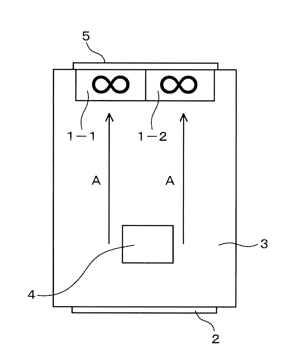
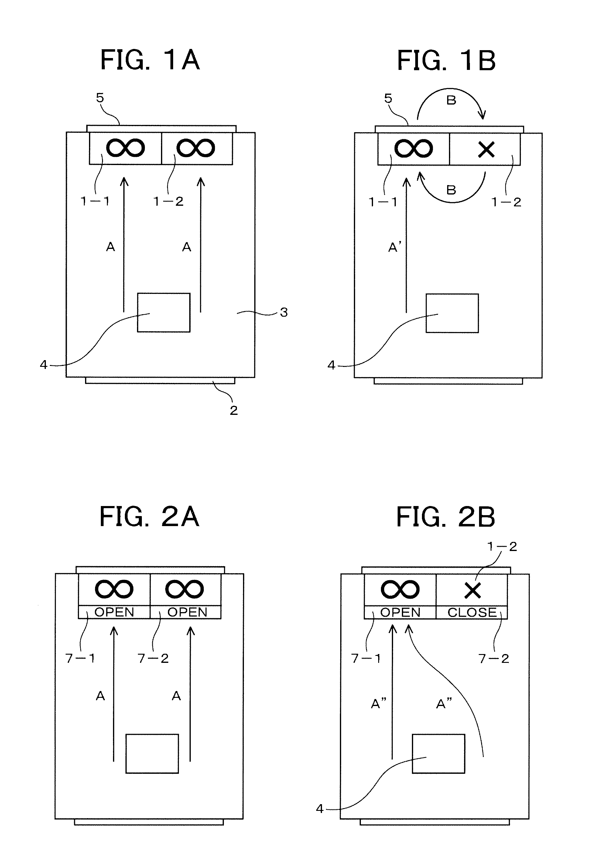
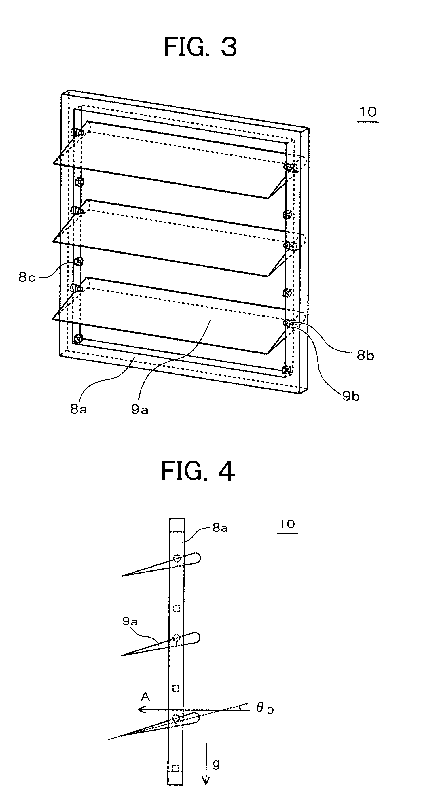
[0032]As a result of studying the aforementioned disadvantageous problems, for example, a wind-pressure shutter blocking a backflow wind is attached to each of plural cooling fans. The wind-pressure shutter includes support shafts extending perpendicular to the exhaust direction of the cooling fan, and a flap that is capable of swinging about the support shafts and has a long portion on the exhaust side and a short portion on the intake side. The flap is swung by action of an air-backflow occurring when...


PUM


Abstract

Plural flaps provided in a wind-pressure shutter are located approximately parallel to a direction of an airflow path, i.e., the airflow path is opened. Thus, the wind-pressure loss of cooling wind passing through the shutter can be reduced to near zero during the normal operation of the fan. If an air-backflow flows from the exhaust vent due to a fan failure, the flap slightly inclined toward the airflow path receives wind pressure of the air-backflow on its surface, thereby swings about the support shaft to close the airflow path.

Description

CLAIM OF PRIORITY[0001]The present application claims priority from Japanese patent application serial no. 2010-100871, filed on Apr. 26, 2010, the content of which is hereby incorporated by reference into this application.BACKGROUND OF THE INVENTION[0002]The present invention relates to a wind-pressure shutter and a cooling fan system and, more particularly, to a wind-pressure fan and a cooling fan system having plural cooling fans and used in electronic equipment.[0003]Recent rapid advances in computerization have led to a common practice of continuously operating electronic equipment such as communication devices, computers, servers and the like for 24 hours a day. As a result, if the equipment goes out of control, it will cause a great deal of inconvenience to customers.[0004]On the other hand, a housing of the equipment is increasingly reduced in size and space. As a result, heat-producing components are densely packed in the housing. In order to prevent a temperature rise in t...

Claims


Application Information

Patent Timeline
Patent Type & Authority Applications(United States)
IPC IPC(8): F28F13/00F16K15/00
CPCF16K1/222F16K1/223F16K15/035F04D25/166H05K7/20209F04D25/14G06F1/20H05K7/20181Y10T137/7898
Inventor KOMABA, SHINJITAMAYAMA, NOBUHIRO
Owner HITACHI LTD
Why Eureka
Try Eureka