Structures of luminous umbrella
Inactive Publication Date: 2011-10-27
TSAI TSUNG HONG
View PDF6 Cites 7 Cited by
- Summary
- Abstract
- Description
- Claims
- Application Information
AI Technical Summary
Benefits of technology
[0016]The present invention aims to improve the problems found in the above-mentioned solutions, which adopt additional or attached light sources, and proposes a solution of using integrated illumination components. The solution proposed is to combine illumination emitter of LED with other umbrella parts. The heat dissipation substrate used for the illumination emitter of LED is exposed and not packaged; it is also firmly mounted on the surface of heat dissipation base of umbrella parts. All the electric components used for the present invention meet the necessary electric insulation and safety requirements. Umbrella parts to be integrated include linkage members on slip ring, rib members on fixed collar and umbrella handle. When the illumination emitter of LED is mounted on the surface of these parts, the overall umbrella structure can be made smaller and lighter, and the flexibility of light so urce design can also be maximized. In particular, when umbrella parts with high heat dissipation capability are used as the heat dissipating fins, the need of heat dissipation required by high-b rightness illumination emitter of LED can be fulfilled. Service life of the illumination emitter of LED can also be significantly prolonged. Moreover, the partly packaged illumination emitter of LED not only becomes smaller in size, but also allows designers to meet various illumination needs, including the degree of brightness and choice of colors, through multiple settings and allocation plans. The flexibility in light design allows light to be completely projected to the inner canopy and to be evenly radiated through the semi-transparent canopy, which turns umbrella into a lantern with both illumination and warning functions when used at night. Umbrella users also become obvious objects when walking at night. In addition, flexible packaging method used for illumination components allows designers to create dazzling effect of colored lighting as well as to achieve the decorative and aesthetic effect with the light projected to the semi-transparent canopy.
Problems solved by technology
Umbrella users also become obvious objects when walking at night.
Method used
View moreImage
Smart ImageViewing Examples
Examples
first embodiment
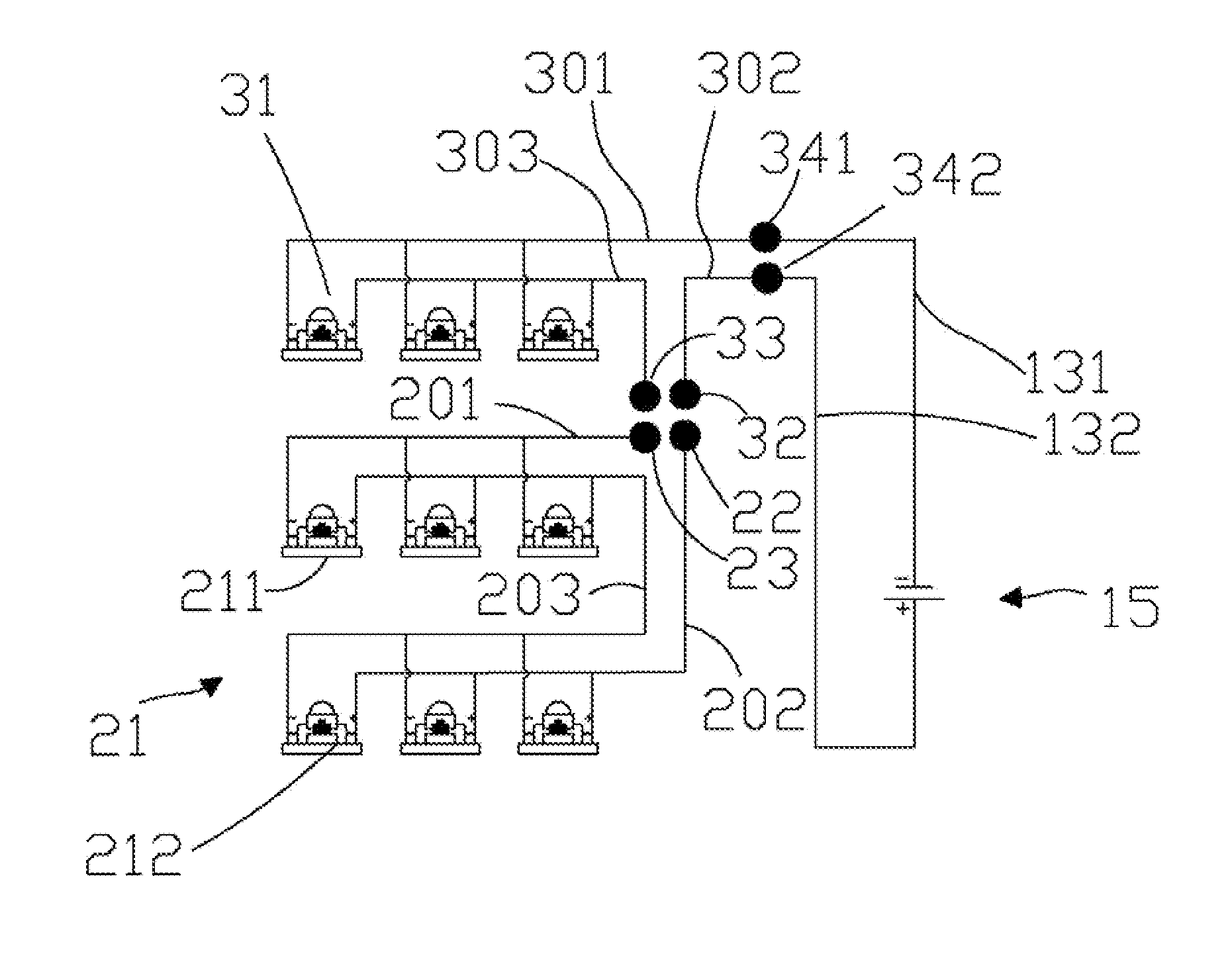
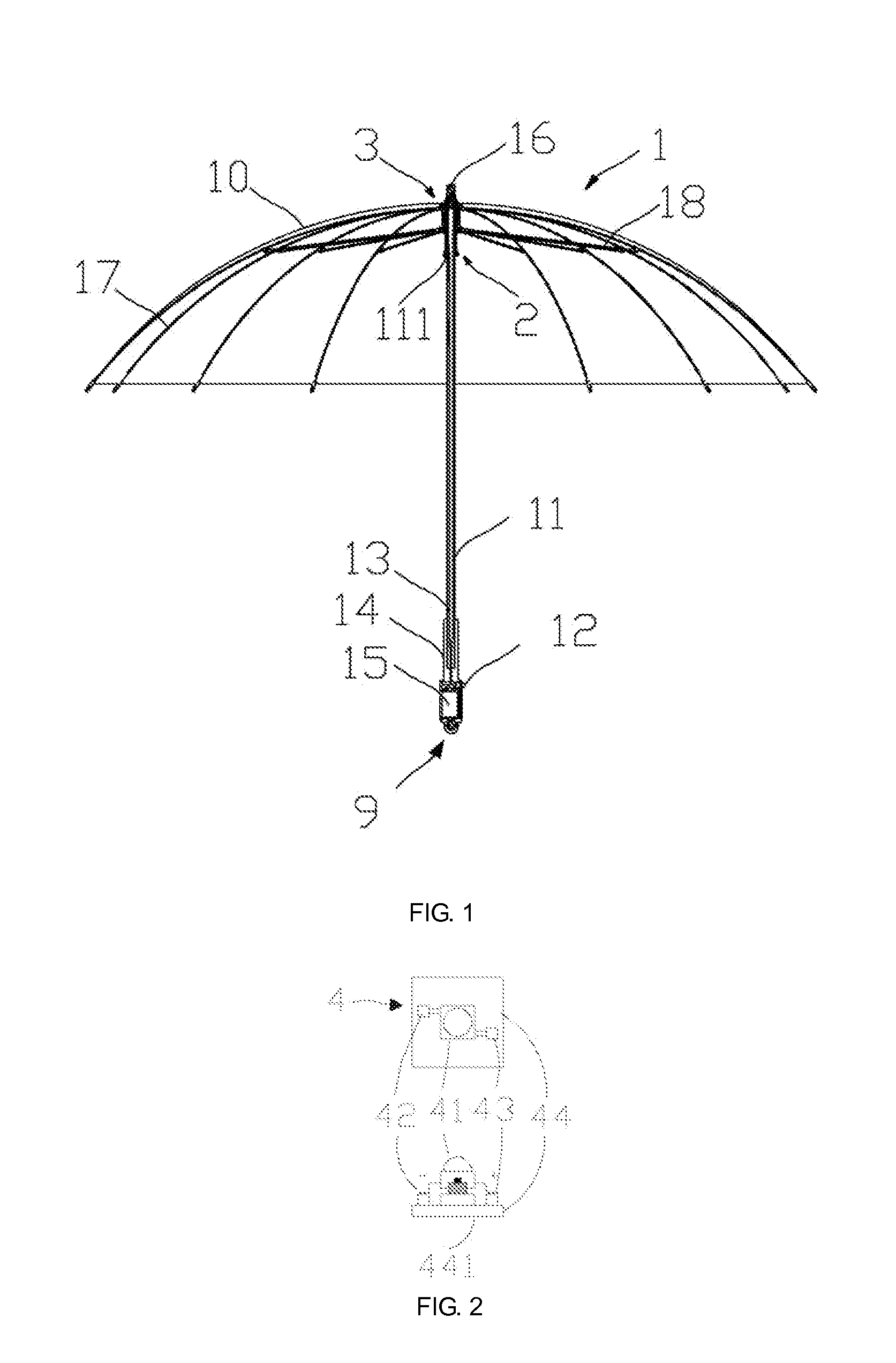
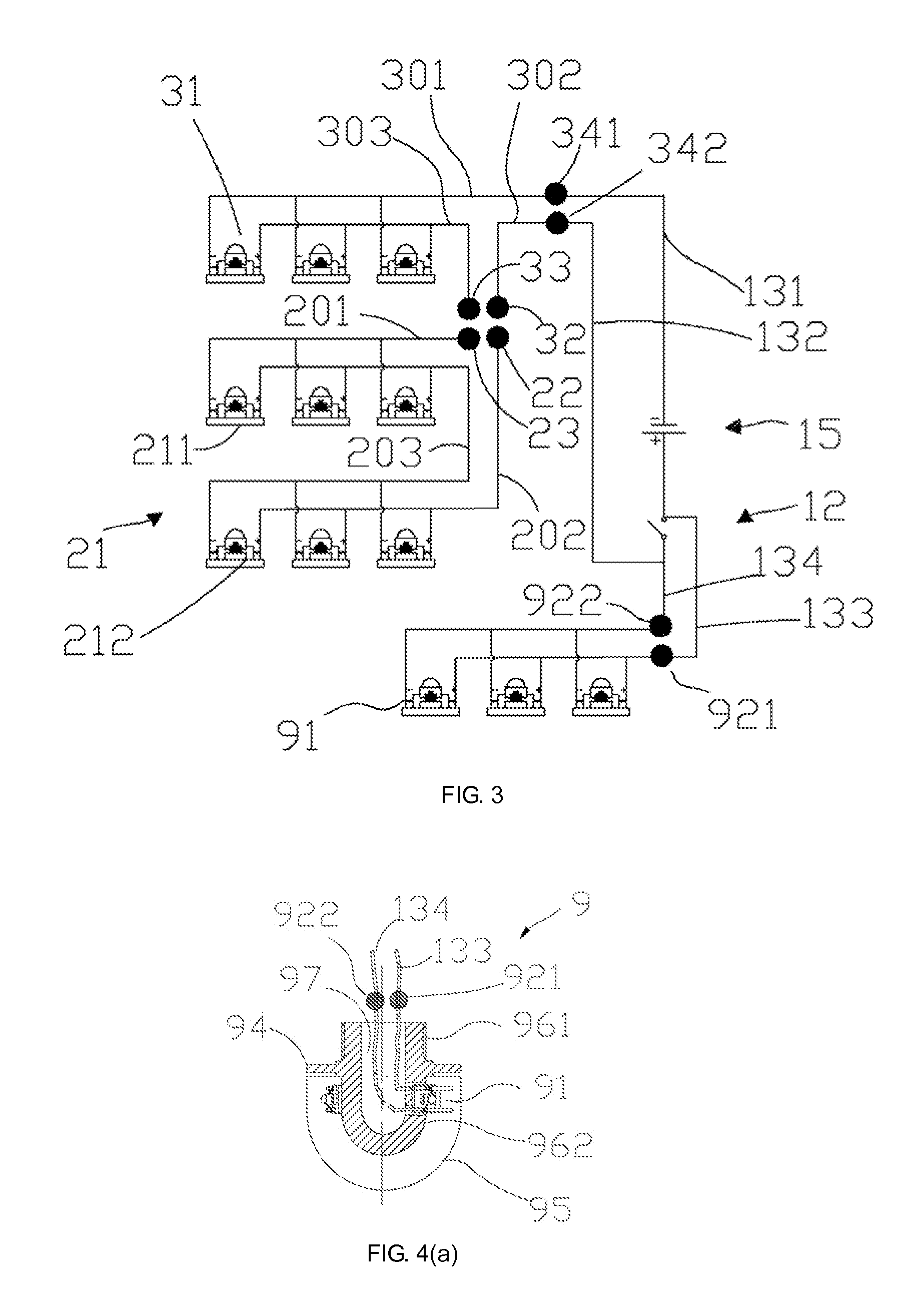
[0018]Refer to FIGS. 1-9 for the first embodiment, which is shown with most details.
second embodiment
[0019]Refer to FIGS. 10-14 for the
third embodiment
[0020]Refer to FIGS. 15-18 for the
Login to View More PUM
 Abstract
The present invention relates to an improvement in the structure of luminous umbrella, using integrated illumination components. The components are ideal for luminous umbrella particularly designed to be used in the evening when visibility is poor, and can be used for other decoration purposes. The integrated illumination components of the present invention are constructed by combining illumination emitter of LED with bases of parts of umbrella, such as linkage members on slip ring, rib members on fixed collar and umbrella handle. When the illumination emitter of LED is mounted on the surface of these parts, the overall umbrella structure can be made smaller and lighter, and the flexibility of light source design can also be maximized. In particular, when base parts with high heat dissipation capability are used as the heat dissipating fins, the full performance of high-brightness illumination emitter of LED can be achieved. The integrated illumination components offer another advantage. With the flexibility of design in the number of illumination emitter of LED and the angle of light projection, the components allow light to be fully projected onto the semi-transparent canopy, which turns luminous umbrella into a lantern with both illumination and warning functions when used at night. Umbrella users thus become obvious objects when walking at night. If color illumination emitter of LED is used, dazzling colored lighting design can be created to the satisfaction of both designers and users, achieving the decorative and aesthetic effect.
Description
FIELD OF THE INVENTION[0001]The present invention relates to the integrated illumination components, which are used to replace traditional umbrella parts to improve the umbrella structure. Integrated illumination components are constructed by combining illumination emitter of LED with bases of parts of umbrella, such as linkage members on slip ring, rib members on fixed collar and umbrella handle. When the illumination emitter of LED is mounted on the surface of these parts, the overall umbrella structure can be made smaller and lighter, and the flexibility of light source design can also be maximized. Application of the present invention turns luminous umbrella into a lantern with both illumination and warning functions, allowing umbrella users to become obvious objects when walking at rainy night and to see roads ahead.BACKGROUND OF THE INVENTION[0002]Luminous umbrella refers to an umbrella equipped with illumination component. Such type of umbrella has long been used to improve u...
Claims
Login to View More Application Information
Patent Timeline
 IPC IPC(8): H05B37/02
CPCA45B3/04A45B2200/1018F21Y2101/02F21V33/0004F21Y2115/10A45B25/00F21L4/00A45B3/02
Inventor CHIEN, HUAN-JANTSAI, TSUNG-HONG
Owner TSAI TSUNG HONG
Features
- R&D
- Intellectual Property
- Life Sciences
- Materials
- Tech Scout
- Unparalleled Data Quality
- Higher Quality Content
- 60% Fewer Hallucinations
Learn More Browse by: Latest US Patents, China's latest patents, Technical Efficacy Thesaurus, Application Domain, Technology Topic, Popular Technical Reports.
© 2025 PatSnap. All rights reserved.Legal|Privacy policy|Modern Slavery Act Transparency Statement|Sitemap|About US| Contact US: help@patsnap.com


