Systems and methods for determining the location and pressure of a touchload applied to a touchpad

a touchload and location technology, applied in the field of user interfaces, can solve the problems of resistive solutions that are not common in practice, touch interfaces that are difficult to use in practice, and existing row/column touchpad approaches that cannot register multiple touches

Active Publication Date: 2011-10-27
SMART SKIN TECH
View PDF16 Cites 148 Cited by
  • Summary
  • Abstract
  • Description
  • Claims
  • Application Information

AI Technical Summary

Problems solved by technology
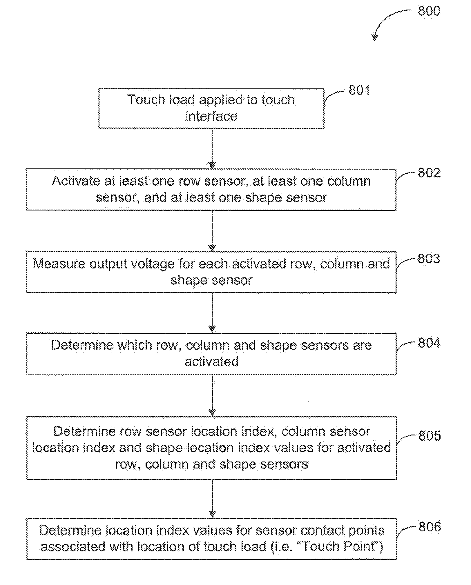
Existing row/column touchpad approaches have limitations on registering multiple touches.
Furthermore, most consumer touch interface devices use capacitive sensing, which are typically not pressure-sensitive because of the sensitivity limitations inherent in capacitive solutions.
Although current resistive techno...

Method used


Image

  • Systems and methods for determining the location and pressure of a touchload applied to a touchpad
  • Systems and methods for determining the location and pressure of a touchload applied to a touchpad
  • Systems and methods for determining the location and pressure of a touchload applied to a touchpad

Examples


Embodiment Construction

[0056]It will be appreciated that numerous specific details are set forth in order to provide a thorough understanding of the exemplary embodiments described herein. However, it will be understood by those of ordinary skill in the art that the embodiments described herein may be practiced without these specific details. In other instances, well-known methods, procedures and components have not been described in detail so as not to obscure the embodiments described herein. Furthermore, this description is not to be considered as limiting the scope of the embodiments described herein in any way, but rather as merely describing the implementation of the various embodiments described herein.

[0057]Some embodiments described herein relate to user interfaces for computing devices. Some embodiments described herein relate to user interfaces for touchscreens for computing devices. Some embodiments described herein relate to user touch interfaces for computing devices that are not part of a t...


PUM


Abstract

A computing device with a multi-touch touch interface having a plurality of rows of contact points and a plurality of columns of contact points. For each other row of contact points, every contact point in the row is connected to form a row sensor. For each other column of contact points, every contact point in the column that is not part of a row sensor is connected to form a column sensor. The contact points that are not part of a row sensor and not part of a column sensor are connected together to form at least one shape sensor. A computing device with a multi-touch touch interface having a plurality of contact points has at least one layer of piezoresistive material, an insulating structure disposed between the plurality of contact points and the piezoresistive material, and a gap between the plurality of contact points and piezoresistive material. A method of providing multi-layered password recognition for a computing device having a touch interface first provides a passcode associated with an alphanumeric symbol to the computing device. The alphanumeric symbol is associated with a passcode pressure level. A touch load is applied to the touch interface and a measured pressure level associated with the applied touch load is determined. Then it is determined whether the measured pressure level corresponds to the passcode pressure level associated with the alphanumeric symbol of the passcode.

Description

CROSS REFERENCE TO RELATED APPLICATION(S)[0001]This application claims the benefit of U.S. Provisional Patent Application Ser. No. 61 / 315,750, filed Mar. 19, 2010, the entire disclosure of which is incorporated herein by reference.BACKGROUND[0002]1. Field of the Invention[0003]The embodiments, described herein relate to user interfaces. More particularly, the systems and methods herein relate to touch interfaces that are able to register multiple, simultaneous touches. Some embodiments described herein relate to pressure-sensitive touch interfaces.[0004]2. Description of the Related Art[0005]Existing row / column touchpad approaches have limitations on registering multiple touches. A third touch position which falls on the same rows and columns as two existing touches will not be registered.[0006]Furthermore, most consumer touch interface devices use capacitive sensing, which are typically not pressure-sensitive because of the sensitivity limitations inherent in capacitive solutions. ...

Claims


Application Information

Patent Timeline
IPC IPC(8): G06F3/041
CPCG06F3/0414G06F21/36G06F2203/04104G06F2203/04103G06F21/83G06F3/04146
Inventor SAYNAC, XAVIER PIERRE-EMMANUELKORMENDY, ARPADMACDONALD, ADAM JOSEPHTHILLAINADARAJAH, KUMARAN
Owner SMART SKIN TECH
Why Eureka
Try Eureka