Method for controlling a watercraft having a surface drive

a technology of surface drive and watercraft, which is applied in the direction of marine propulsion, vessel construction, instruments, etc., can solve the problems of hysteresis and preventing frequent switching between, and the angle cannot be corrected by rotational speed deviation, so as to increase rotational speed and/or speed, linearly decrease, and increase speed

Inactive Publication Date: 2011-10-27
ZF FRIEDRICHSHAFEN AG
View PDF0 Cites 23 Cited by
  • Summary
  • Abstract
  • Description
  • Claims
  • Application Information

AI Technical Summary

Benefits of technology

[0011]In a development of the method according to the present invention, the first threshold control angle to be exceeded is greater than the second threshold control angle below threshold. This hysteresis prevents frequent switching between the automatic adjustment of the trim angle and stand-by operating modes for control angles within the range of the first threshold control angle.
[0015]Another version offers the possibility that the maximum adjustable control angle in a first driving mode, which extends from the first rotational speed limit up to a second rotational speed limit, is still at a maximum and in every subsequent faster driving mode, in which the trim angle is automatically adjusted according to a different operating mode, the maximum adjustable control angle remains constant for each driving mode and decreases at the transition to the next higher driving mode. A stepped reduction of the maximum adjustable control angle is thus created throughout the entire operating mode with increasing rotational speed and / or speed.

Problems solved by technology

The trim angle has to be manually adjusted, since due to the tilted position of the watercraft while turning the curve, the propeller on the outside curve is no longer running in the water upon reaching the first threshold control angle and the automatic adjustment of the trim angle can no longer correct the rotational speed deviation.
This hysteresis prevents frequent switching between the automatic adjustment of the trim angle and stand-by operating modes for control angles within the range of the first threshold control angle.

Method used


Image

  • Method for controlling a watercraft having a surface drive
  • Method for controlling a watercraft having a surface drive
  • Method for controlling a watercraft having a surface drive

Examples


Embodiment Construction

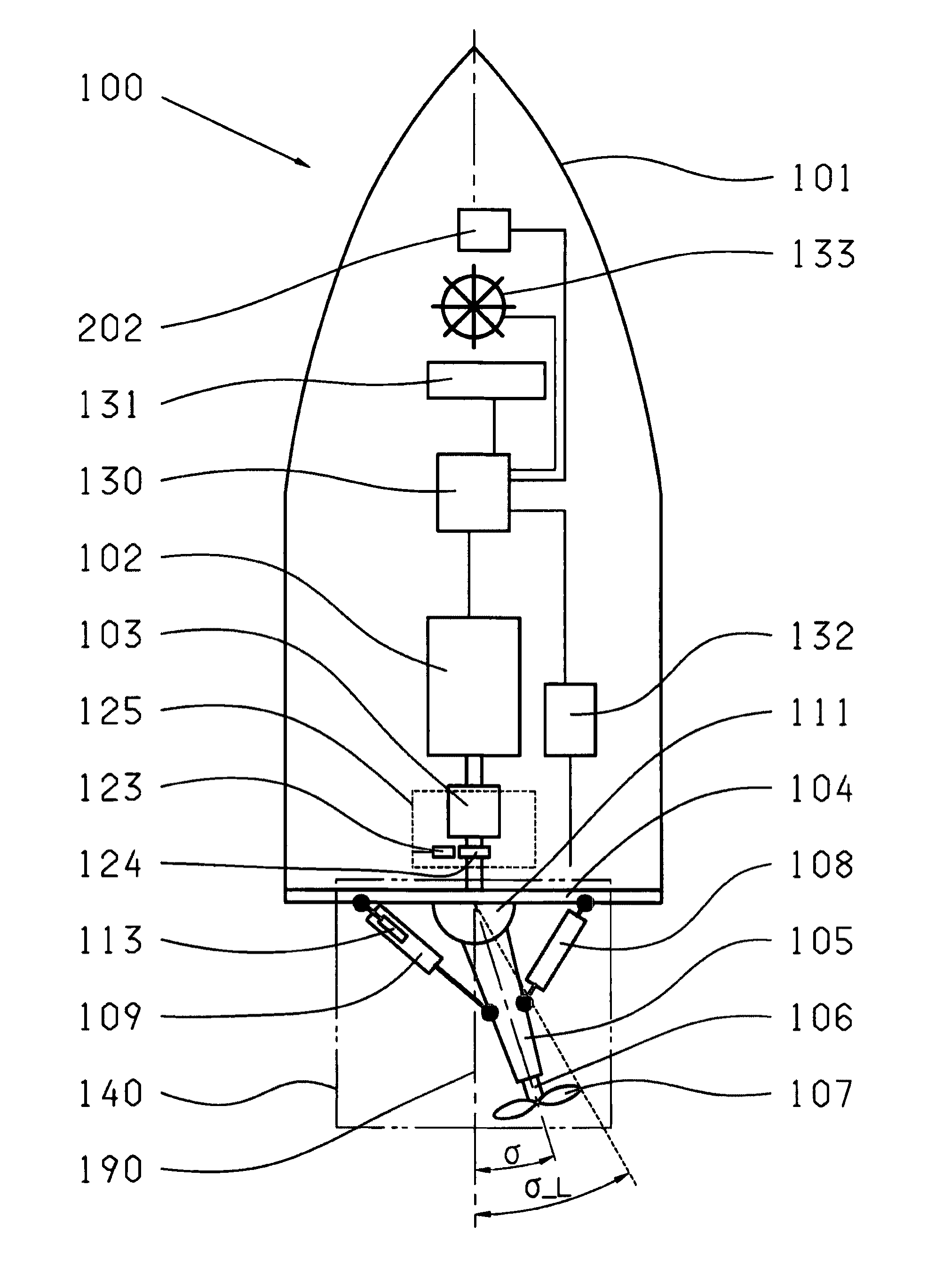
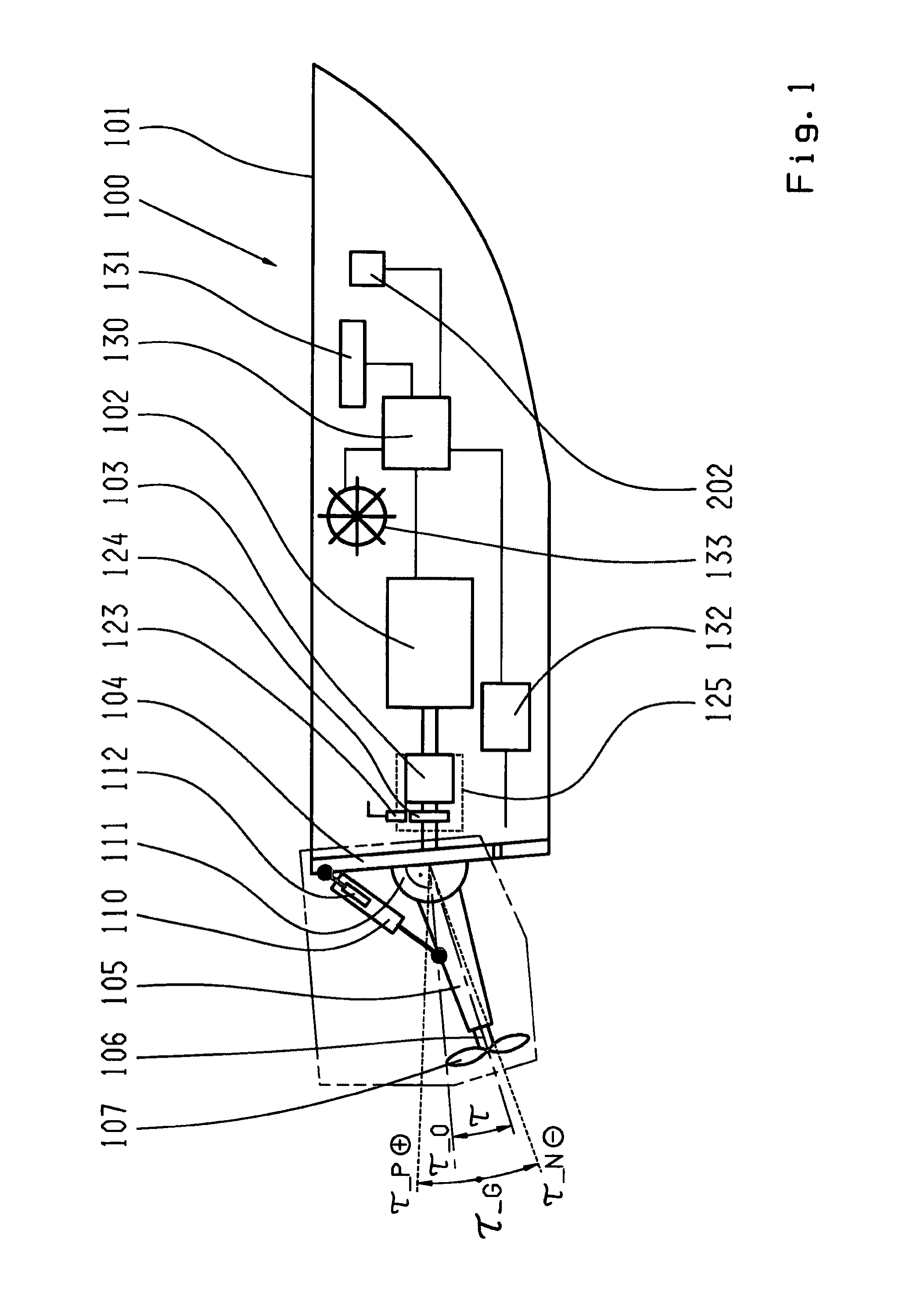
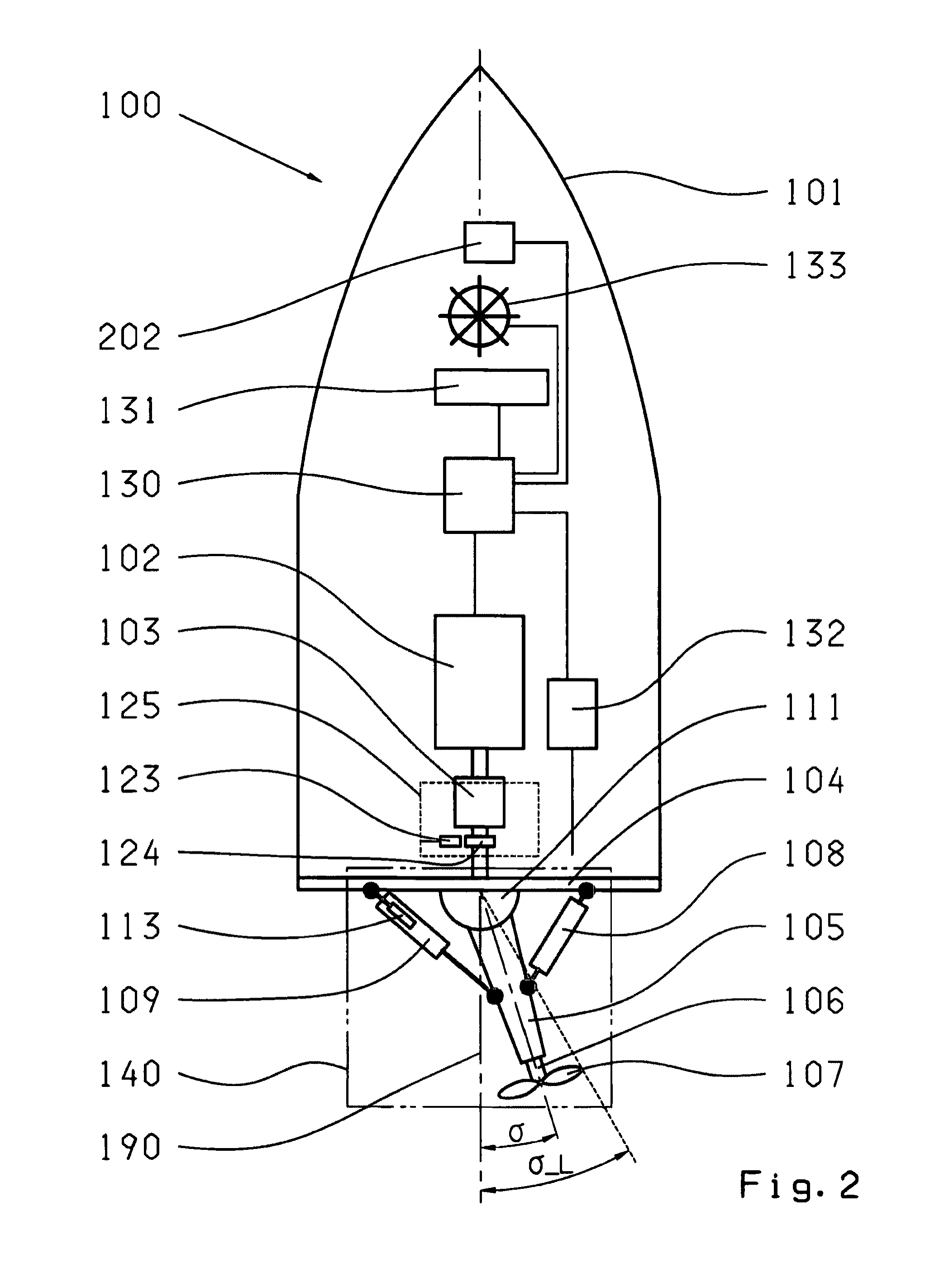
[0022]FIGS. 1 and 2 show a watercraft 100 with surface drive. The drive unit 140 of the surface drive is arranged at the stern side of the hull 101 of the watercraft 100 and connected with the transom 104. The drive unit 140 consists of the thrust tube 105 with the propeller shaft 106 and the propeller 107 as well as the control actuator system 108, 109 and the trim actuator system 110. The pivot-mounted propeller shaft 106, which has the propeller 107 attached to its stern end, is pivotally-mounted at the center of the thrust tube 105. The thrust tube 105 with the transom 104 and the propeller shaft 106 with the power train 125 are connected and pivotally-mounted at the articulation point 111. The power train 125 contains a transmission 103. The rotational speed sensor 123 measures the rotational speed n at a port plate 124, for example, whose signal is acquired by an electronic control unit 130. The pivoting movement about a horizontal plane, also referred to as control movement, ...


PUM


Abstract

A method of controlling a watercraft having a drive which can be pivoted about a control angle. According to the method, a maximum adjustable control angle is automatically reduced by a defined gradient with an increasing speed. The drive is configured as a surface drive comprising at least two drive units, and the drive units are adjusted in the vertical direction about a trim angle in a pre-adjustable automatic operating mode (301). During a driving mode in which the maximum speed is reached, the adjustment of the trim angle (τ), once it exceeds a first threshold control angle (σ—41) which is smaller than the maximum adjustable control angle (σ_L), exits the automatic operating mode (301) and switches to a stand-by operating mode (300) in which the trim angle (τ) is manually adjusted until it falls below a second threshold control angle (σ—42) and the automatic operating mode (301) is re-activated.

Description

[0001]This application is a National stage completion of PCT / EP2007 / 063439 filed Dec. 6, 2007, which claims priority from German patent application serial no. 10 2007 048 060.3 filed on Oct. 5, 2007.FIELD OF THE INVENTION [0002]The invention relates to a method for controlling a watercraft having a surface drive.BACKGROUND OF THE INVENTION [0003]In fast, motor-driven watercrafts, particularly those having a surface drive, the hull is in a planing state at higher speeds, with the stern just lying partially in the water. When turning curves and during the related tilted position of the watercraft, the point of contact with the water shifts to the side surface of the bottom of the hull causing the force application of the driving resistance at the hull to change and generate a moment. From a critical control angle and the resultant tight turning radius the thus generated moment is so high that starting at a certain speed the watercraft is deflected from its path and may capsize.[0004]T...

Claims


Application Information

Patent Timeline
Patent Type & Authority Applications(United States)
IPC IPC(8): B63H5/125
CPCB63H2001/185B63H5/125G05D1/0875B63H20/08
Inventor CHIECCHI, ANDREA
Owner ZF FRIEDRICHSHAFEN AG
Why Eureka
Try Eureka