
Game device

Inactive Publication Date: 2006-02-28
SEGA CORP
View PDF15 Cites 24 Cited by
  • Summary
  • Abstract
  • Description
  • Claims
  • Application Information

AI Technical Summary

Benefits of technology

[0031]According to the above structure, when the opponent's machine (or opponent's bike) which is the second object does not exist nearby, it will be easy for the player to grasp the relative position relationship between the player's machine (or player's bike) which is the first object and the opponent's bike since the display reduction (or display magnification) of the small screen is largely set. Furthermore, if an opponent's bike is not nearby, the display reduction of the small screen will be set small thereby enabling the player to see the shape of the racecourse in a wide field. This is a preferable game supporting screen for games that proceed races while engaging in battles. Moreover, frequent switching of the screen may be avoided.
[0051]According to the above structure, the content to be displayed on the small screen is, whether magnified or reduced, displayed in an adequate display magnification (or scale) in accordance with the prescribed conditions during the game progress. Thereby, the small screen having a small display area may be used as an overall display or a partial display to effectively show the necessary information.
[0057]Preferably, the display altering step further gradually magnifies or reduces the outer frame of the field including the first object displayed on the small screen without changing the overall size of the small screen by gradually changing the display magnification of the small screen.

Problems solved by technology

Thereby, since information of the player's machine and the surrounding information thereof will be relatively displayed small, it is difficult to obtain detailed information.
In consideration of the above points, if only the vicinity of the object is displayed in order to provide detailed surrounding supplementary information, there was a problem in that movement of the player's machine at fast speeds and the prediction of the game progress became difficult since it would be difficult to grasp the situation of the next progress (e.g., a situation such as an object controlled by another player or a computer program (“opponent's machine”) comes charging toward the player's machine).

Method used


Image

  • Game device
  • Game device
  • Game device

Examples


Embodiment Construction

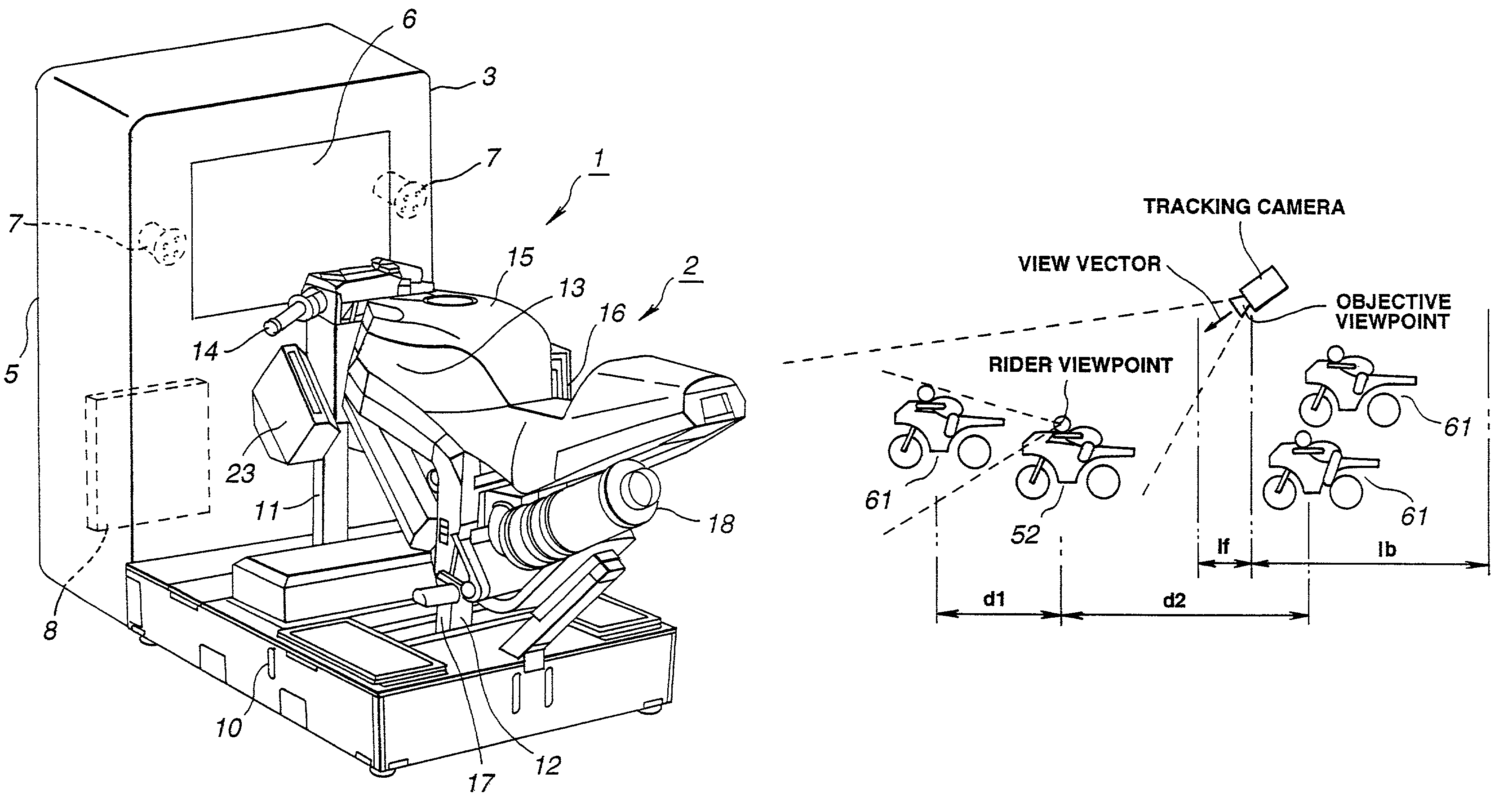
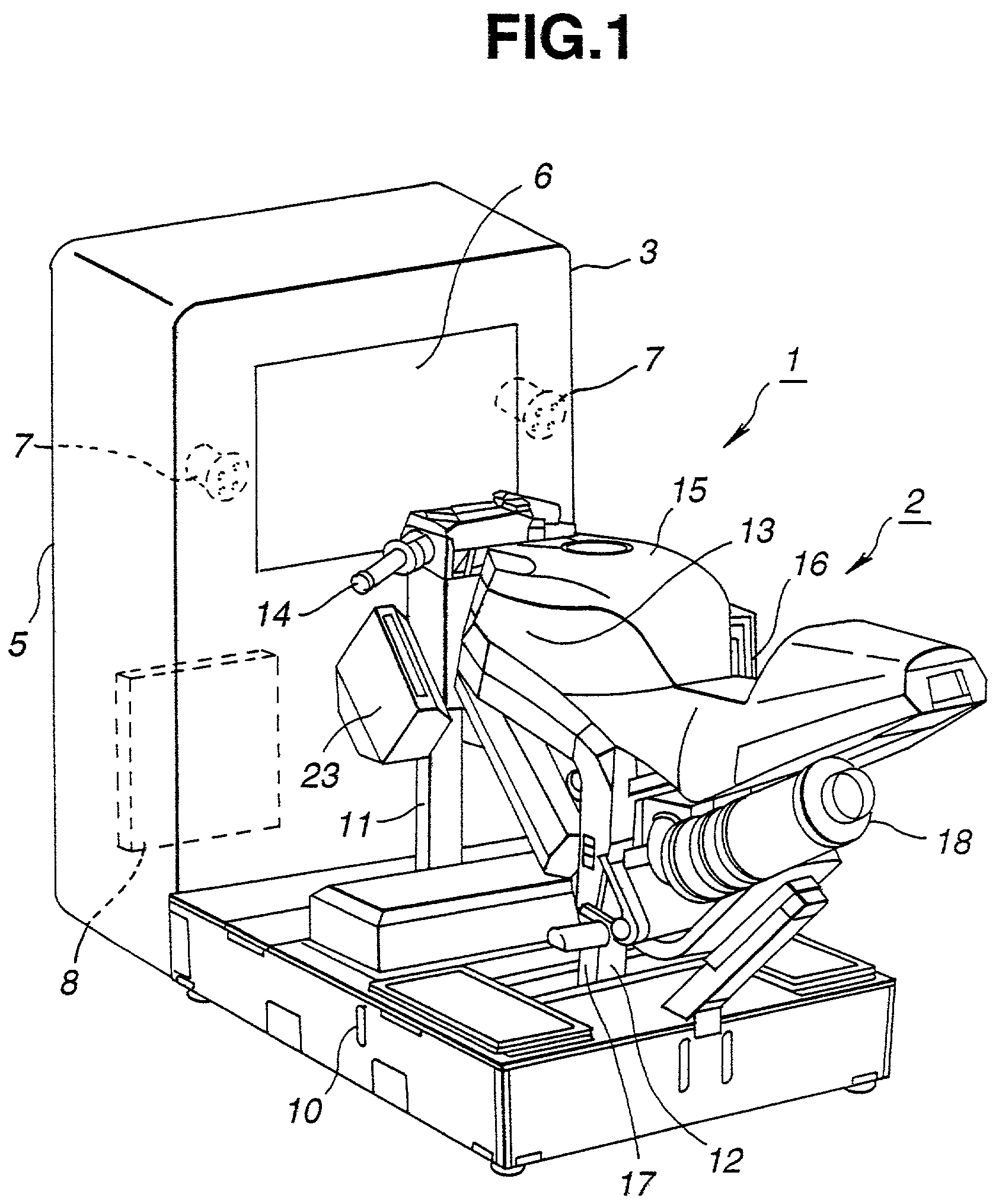
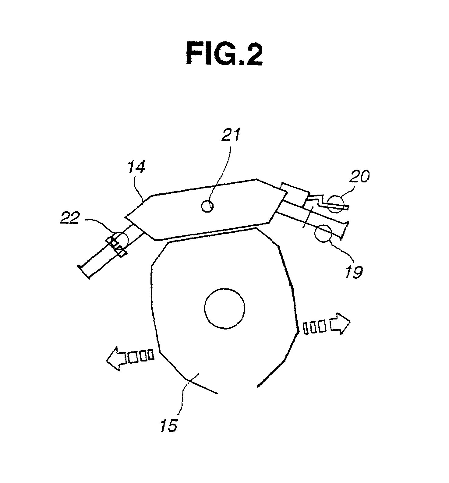
[0079]Embodiments of the present invention are hereinafter explained with reference to the drawings. FIG. 1 is a perspective diagram showing an example of an embodiment of the game device for driving games according to the present invention. FIG. 2 is a plane view of the handle of the operating apparatus in the style of a motorcycle.

[0080]The game device 1 which employs an embodiment of the present invention is structured of, as shown in the diagram, an operating apparatus 2 resembling a shape of a motorcycle (“motorcycle-type operating apparatus”) which mainly forms operation signals and also performs kick back motions, and a game machine main body 3 provided at the front side of this motorcycle-type operating apparatus 2. This game machine main body 3 is structured of a cage body 5 which is a rectangular parallelepiped of a prescribed size, a display 6 which is provided on one face of this cage body 5, a speaker 7 which composes a portion of the sound device provided inside this c...


PUM


Abstract

A game device, which monitors with a virtual camera a picture of a game being proceeded in a virtual space by a first object controlled by a player and a second object controlled by a computer or an opponent and displays a picture on the screen of a monitor, includes a camera position switch ordering unit for issuing switching orders to switch the position of the virtual camera to a first position which shows the front of the first object and to a second position which shows the front of the first object from the rear of the first object, and a symbol displaying unit for displaying a symbol representing the second object on the monitor screen in correspondence with the switching order to switch the position of the virtual camera to the first position upon the second object existing behind the first object.

Description

[0001]This application is a Divisional of U.S. patent application Ser. No. 09 / 150,595, filed Sep. 10, 1998, now U.S. Pat. No. 6,409,596 which issued on Jun. 25, 2002.BACKGROUND OF THE INVENTION[0002]1. Field of the Invention[0003]The present invention generally relates to a game device. More particularly, it relates to a game device loaded with a program for game play wherein an object simulating the likes of a car, for example, is placed on a virtual space and a picture of such object moving in response to the operation from the player is displayed on the TV screen.[0004]2. Description of the Related Art[0005]Pursuant to the advancement of computer technology, there is a demand for game devices with clearer and more realistic images regardless of such game device being for home use or business use. Generally, a game device comprises a game device body with a built-in computer device for performing previously stored game programs, an operation apparatus for providing to the computer...

Claims


Application Information

Patent Timeline
IPC IPC(8): A63F13/00A63F13/10
CPCA63F13/005A63F13/10A63F2300/1062A63F2300/303A63F2300/8017A63F2300/64A63F2300/6661A63F2300/6676A63F2300/6684A63F2300/307A63F13/5378A63F13/57A63F13/5255A63F13/525A63F13/5258A63F13/245A63F13/803A63F13/53
Inventor HAYASHIDA, YASUHIROUENO, ATSUSHIYASUDA, TAISHI
Owner SEGA CORP
Learn More