Magnetic snap fastener

a magnetic snap and fastener technology, applied in the direction of magnets, snap fasteners, magnetic bodies, etc., can solve the problems of affecting the functioning of the magnetic sensor component of the mobile electronic device, the locking force of the magnetic snap fastener may not be sufficient to hold the bag, and the storage items may fall to the ground, etc., to achieve simple structure, prevent disconnection, and enhance connection tightness

Inactive Publication Date: 2011-11-03
DOTS TECH
View PDF16 Cites 26 Cited by
  • Summary
  • Abstract
  • Description
  • Claims
  • Application Information

AI Technical Summary

Benefits of technology

[0005]The present invention has been accomplished under the circumstances in view. It is the main object of the present invention to provide a magnetic snap fastener, which facilitates operation and prevents accidental disconnection.
[0007]When the male snap member and the female snap member are attached together, the two magnetic attractive members attract each other to enhance the connection tightness between the socket hole of the socket and the engagement portion of the male snap member, preventing disconnection between the male snap member and the female snap member. Thus, the magnetic snap fastener has the characteristics of simple structure, high locking power and high practical value.

Problems solved by technology

If the power of magnetic attraction is insufficient, the magnetic snap fastener may be unlocked accidentally by an external force, and the storage items may fall to the ground.
Further, when too much storage items are received in the bag, the locking force of the magnetic snap fastener may be insufficient to hold the bag in the closed position.
When a magnetic snap fastener having a high power of magnetic attraction is used in a bag for mobile electronic device, such as cell phone or digital camera, the magnetic lines of force generated by the magnetic snap fastener may interfere with the functioning of the magnetic sensor component of the mobile electronic device.
These problems give a barrier to the use of products that use a magnetic snap fastener.

Method used


Image

  • Magnetic snap fastener
  • Magnetic snap fastener
  • Magnetic snap fastener

Examples


first embodiment

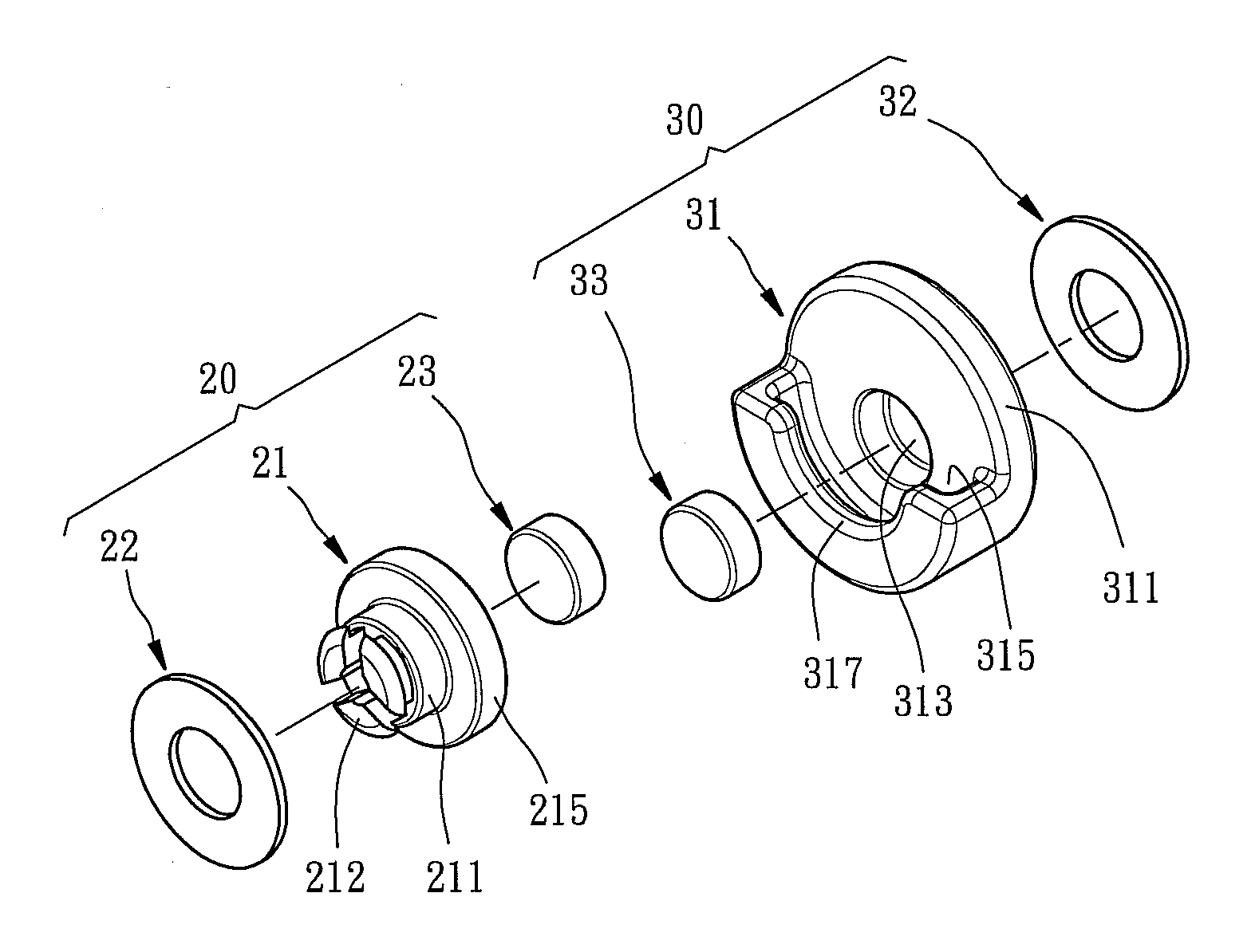
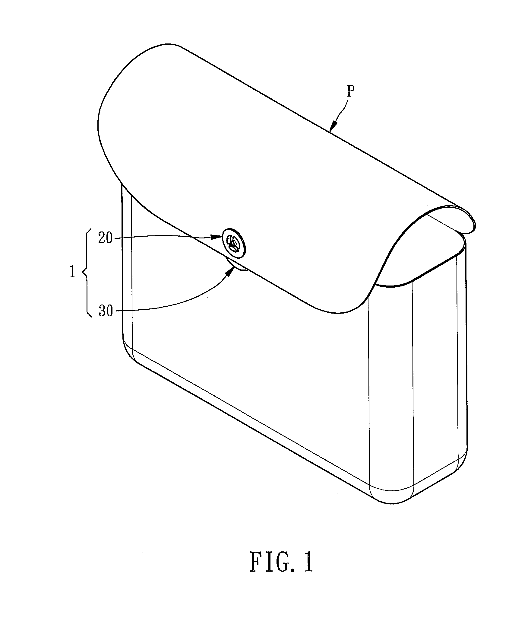
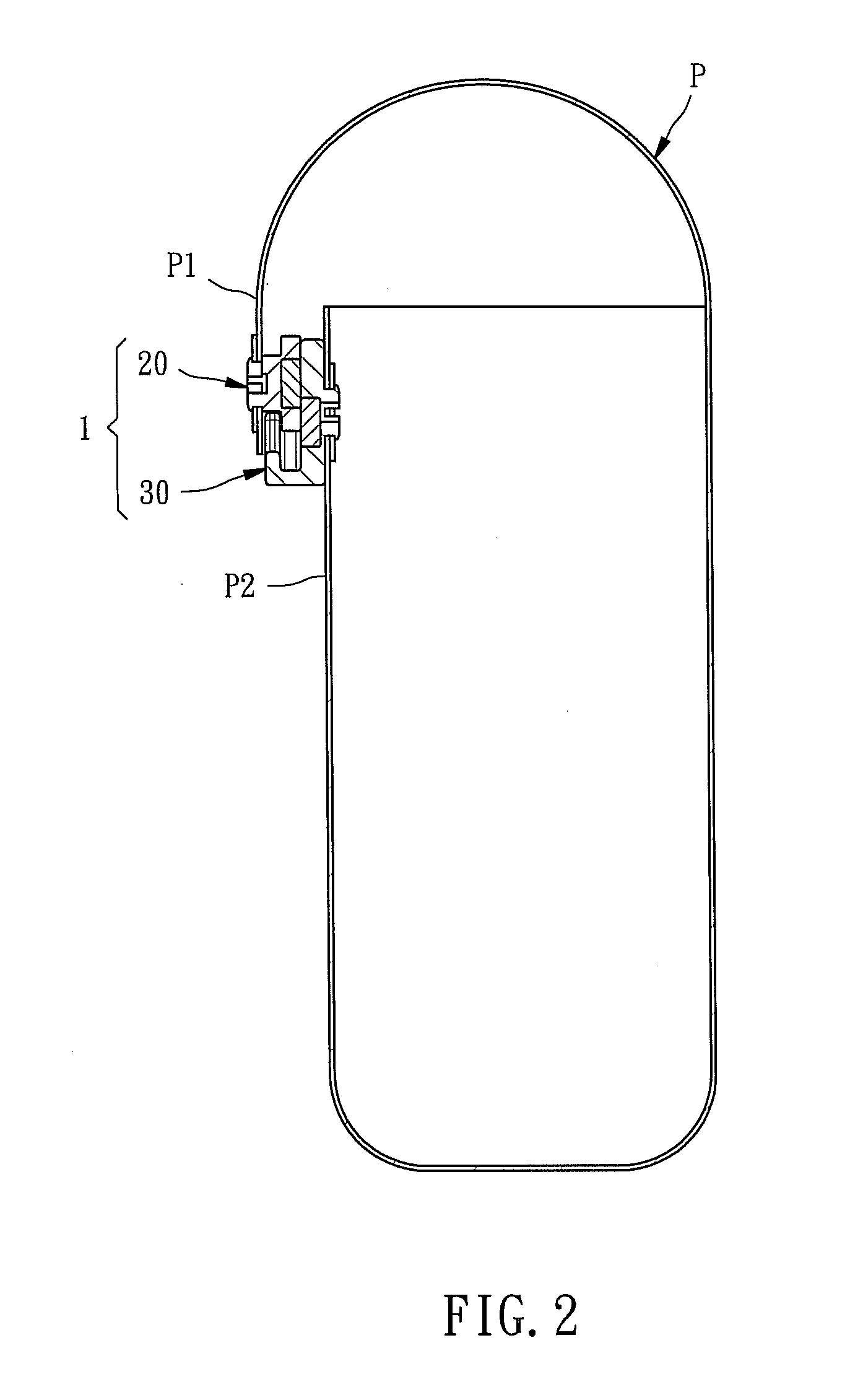
[0020]Referring to FIGS. 1˜6, a magnetic snap fastener 1 in accordance with the present invention is shown installed in a container (for example, handbag) P. The magnetic snap fastener 1 comprises a male snap member 20 and a female snap member 30 respectively installed in a first part (cover member) P1 and a second part (body member) P2 of the container (handbag) P.

[0021]The male snap member 20 consists of a stud 21, an annular plate 22 and a magnetic attractive member 23. The stud 21 comprises an engagement portion 215, a recessed hole 213 located on one side of the engagement portion 215, a shank portion 211 located on the opposite side of the engagement portion 215, and three hooked portions 212 equiangularly arranged on the distal end of the shank portion 211 remote from the engagement portion 215. The magnetic attractive member 23 is fixedly mounted in the recessed hole 21 and kept in flush with the outside wall of the engagement portion 215 of the stud 21. The diameter of the ...

fourth embodiment

[0029]This fourth embodiment achieves the same effects as the aforesaid first, second and third embodiments.

[0030]Further, other modifications may be made thereunto without departing from the spirit and scope of the invention. For example, both the magnetic attractive member of the male snap member and the magnetic attractive member of the female snap member can be magnets (permanent magnets); alternatively, one of the magnetic attractive members of the male and snap members can be a magnet (permanent magnet) and the other can be a magnetically conductive member.

[0031]Further, a floating control member (not shown) may be used with the magnetic snap fastener. When the male snap member and the female snap member are fastened together, the floating control member is exposed to the outside of the female snap member for operation by the user to disengage the male snap member from the socket of the female snap member. The use of the floating control member enhances the application of the ...


PUM


Abstract

Installed in a container for locking opposing first part and second part of the container, a magnetic snap fastener is disclosed to include a male snap member having a stud with an engagement portion and a magnetic attractive member fixedly mounted in one side of the engagement portion, and a female snap member having a socket with a socket hole for receiving the engagement portion of the stud of the male snap member and a magnetic attractive member fixedly mounted in one side of the socket for attracting the magnetic attractive member of the male snap member when the engagement6 portion of the male snap member is attached to the socket hole in the female snap member.

Description

BACKGROUND OF THE INVENTION[0001]1. Field of the Invention[0002]The present invention relates to snap fastening means and more particularly, to a magnetic snap fastener, which facilitates operation and prevents accidental disconnection.[0003]2. Description of the Related Art[0004]Conventional magnetic snap fasteners are intensively used in personal items, such as cell phone bags, handbags, purses, and etc. When designing a magnetic snap fastener, the size of the magnetic members and the power of magnetic attraction are important factors. If the power of magnetic attraction is insufficient, the magnetic snap fastener may be unlocked accidentally by an external force, and the storage items may fall to the ground. Further, when too much storage items are received in the bag, the locking force of the magnetic snap fastener may be insufficient to hold the bag in the closed position. When a magnetic snap fastener having a high power of magnetic attraction is used in a bag for mobile elect...

Claims


Application Information

Patent Timeline
Patent Type & Authority Applications(United States)
IPC IPC(8): A44B17/00
CPCA45C13/1069Y10T24/32A44B17/0064H01F7/0263
Inventor WU, RACE
Owner DOTS TECH
Why Eureka
Try Eureka