
Operating buttons with disappearing triangular indicia

Inactive Publication Date: 2011-11-03
LUTRON TECH CO LLC
View PDF1 Cites 93 Cited by
  • Summary
  • Abstract
  • Description
  • Claims
  • Application Information

AI Technical Summary

Benefits of technology

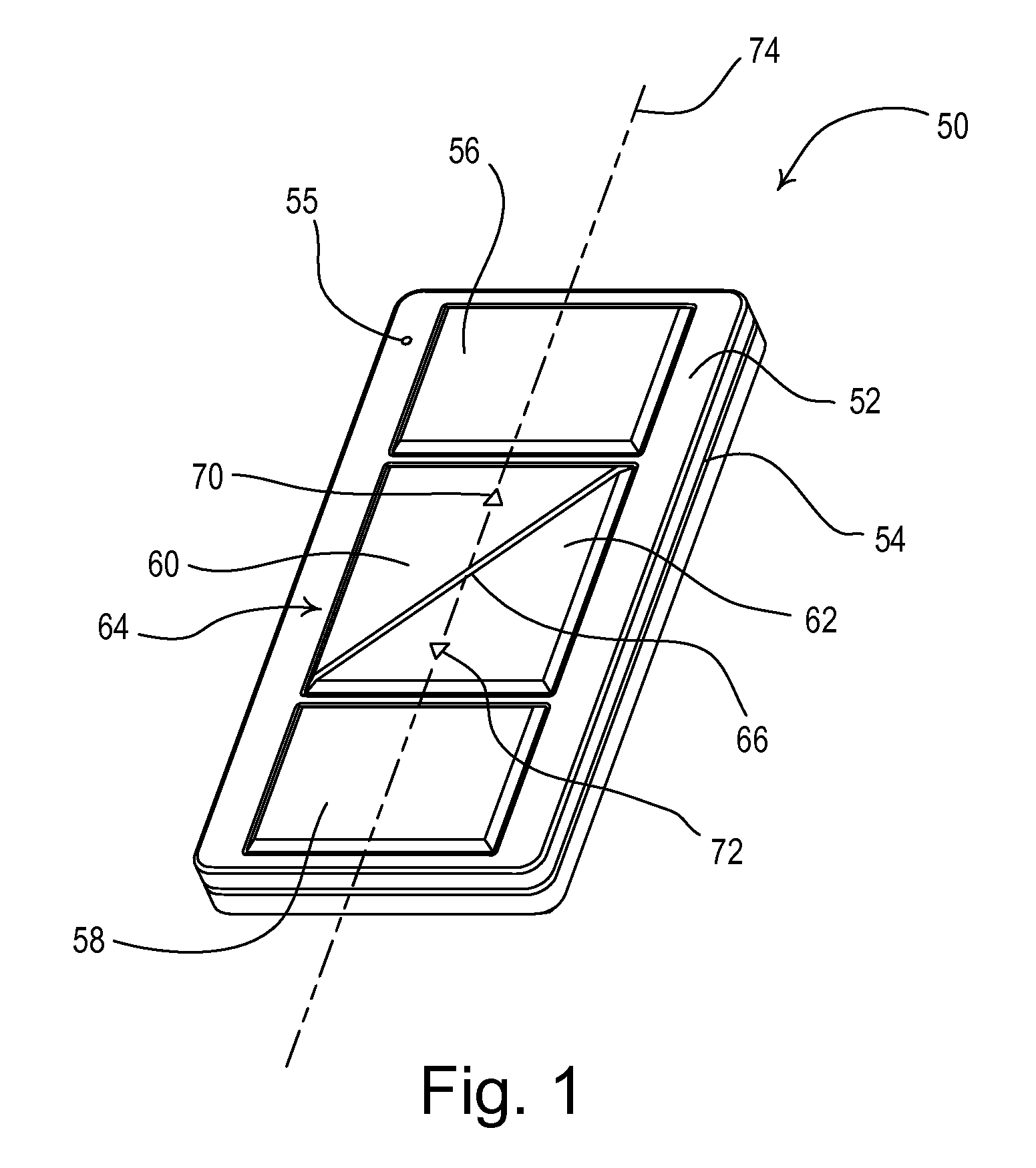
[0004]In accordance with one aspect of the present invention, there is provided directional indicators for first and second control buttons of an electrical control device for indicating the direction of a change initiated by the actuation of the control button. The first and second control buttons have identical surface areas of the same given color. Each of said first and second buttons receive at least one directional indicator; the directional indicators including at least first and second narrow lines which join at a vertex to define an arrow pointing in a direction related to the direction of change caused by the actuation of its respective button. Each of the narrow lines have a length of less than about 100 mils (i.e., thousands of an inch) whereby the visibility of the lines to the eye is substantially reduced as an observer's distance from the electrical control device is increased.

Problems solved by technology

However, the large and often diversely colored indicia impart an undesired cluttered appearance to the device surface.

Method used


Image

  • Operating buttons with disappearing triangular indicia
  • Operating buttons with disappearing triangular indicia
  • Operating buttons with disappearing triangular indicia

Examples


Embodiment Construction

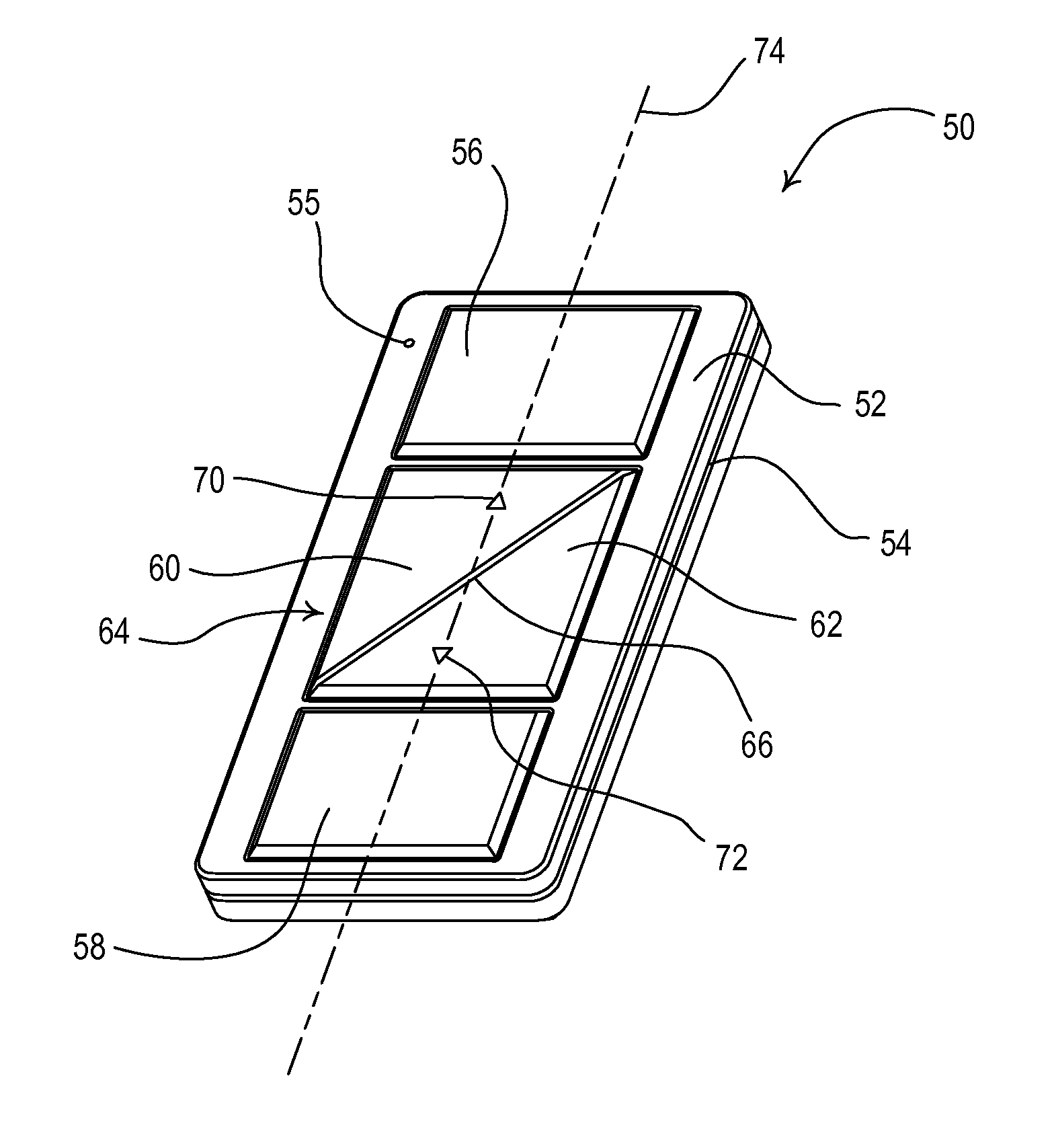
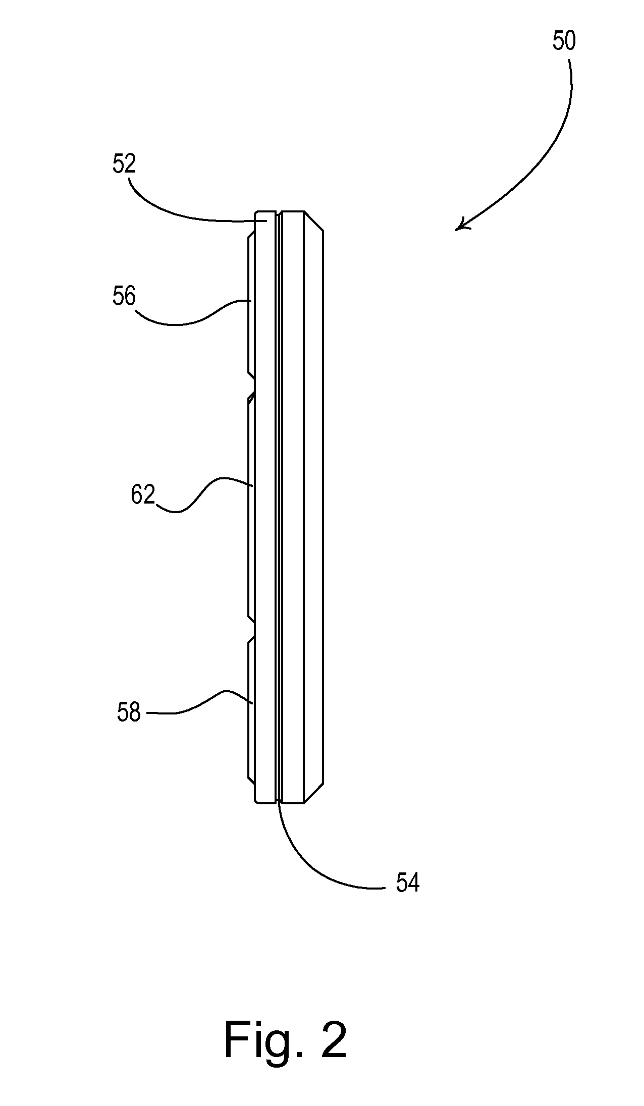
[0029]Referring to the drawing Figures in which reference numerals refer to like elements, FIGS. 1 and 2 show a hand-held remote control device 50 for a control system which may be used, for example, for control of the energization of a load, such as a lighting load, a motor load, or the like. The remote control device 50 may have a rectangular plastic body (or bezel) 52 which has a peripheral slot 54 joining two halves of the device which enclose the device electronics and battery (not shown). The remote control device 50 may have a length of about 3 inches, a width of about 1 inch and a thickness about ¼ inch. These are non-critical dimensions. A visual indicator 55 (such as a light-emitting diode) may be placed in body 52 to provide feedback to a user regarding the operation of the remote control device 50. The body 52 receives rectangular on and off control buttons 56, 58 respectively, which may be pressed by an operator to for turning full on and full off the energization of sa...


PUM


Abstract

Directional indicators on the control buttons of an electrical control for a light dimmer or a motor controller are formed by triangular lines with vertices pointing away from one another and in a direction related to the change initiated by pressing the related button. The indicia are formed by narrow lines of length less than about one hundred thousands of an inch, and tend to disappear from view as an observer is farther away from the control buttons. The buttons are formed of right triangles with adjacent spaced hypotenuses and fit into a rectangular area. On / off rectangular buttons of the same color as the control buttons are atop and below the rectangular area.

Description

FIELD OF THE INVENTION[0001]This invention relates to control devices for electrical loads and more specifically relates to control devices in which actuation buttons for driving loads in opposite directions have self-teaching indicators that are clearly visible to an operator only when the operator is close to the actuating buttons.DESCRIPTION OF RELATED ART[0002]Hand-held remote control devices and wall mounted control devices are well known for the control of electrical loads such as lamps which are to be controllably dimmed and motors which drive drapes or shades towards open and closed positions. Such control devices usually have operating buttons with indicators of their function such as the dimming direction of a lamp load or the drive direction of a motor. The indications are frequently of large size and of color which contrasts with the surface color of the button. As a result, the indicia are easily observable from all distances from the control. However, the large and oft...

Claims


Application Information

Patent Timeline
IPC IPC(8): H01H9/00
CPCH01H2009/187H01H9/18
Inventor ZAHARCHUK, WALTER S.JACOBY, JR., ELLIOT G.BUTLER, NATHANSPIRA, JOEL S.
Owner LUTRON TECH CO LLC
Learn More