Method of Striking a Lamp in an Electronic Dimming Ballast Circuit

a technology of electronic dimming ballast and lamp, which is applied in the direction of electric variable regulation, process and machine control, instruments, etc., can solve the problems of inconvenient operation, inability to dim the high-efficiency light source to very low output levels, and inability to provide a continuous spectrum of light outpu

Inactive Publication Date: 2011-11-03
LUTRON TECH CO LLC
View PDF2 Cites 56 Cited by
  • Summary
  • Abstract
  • Description
  • Claims
  • Application Information

AI Technical Summary

Problems solved by technology

Unfortunately, continuous-spectrum light sources, such as incandescent and halogen lamps, tend to be very inefficient.
However, a typical high-efficiency light source does not typically provide a continuous spectrum of light output, but rather provides a discrete spectrum of light output.
However, a high-efficiency light source cannot be typically dimmed to very low output levels.
As more people begin using high-efficiency light sources—typically to save energy—they are somewhat dissatisfied with the overall performance of the high-efficiency light sources.

Method used


Image

  • Method of Striking a Lamp in an Electronic Dimming Ballast Circuit
  • Method of Striking a Lamp in an Electronic Dimming Ballast Circuit
  • Method of Striking a Lamp in an Electronic Dimming Ballast Circuit

Examples


Embodiment Construction

[0026]The foregoing summary, as well as the following detailed description of the preferred embodiments, is better understood when read in conjunction with the appended drawings. For the purposes of illustrating the invention, there is shown in the drawings an embodiment that is presently preferred, in which like numerals represent similar parts throughout the several views of the drawings, it being understood, however, that the invention is not limited to the specific methods and instrumentalities disclosed.

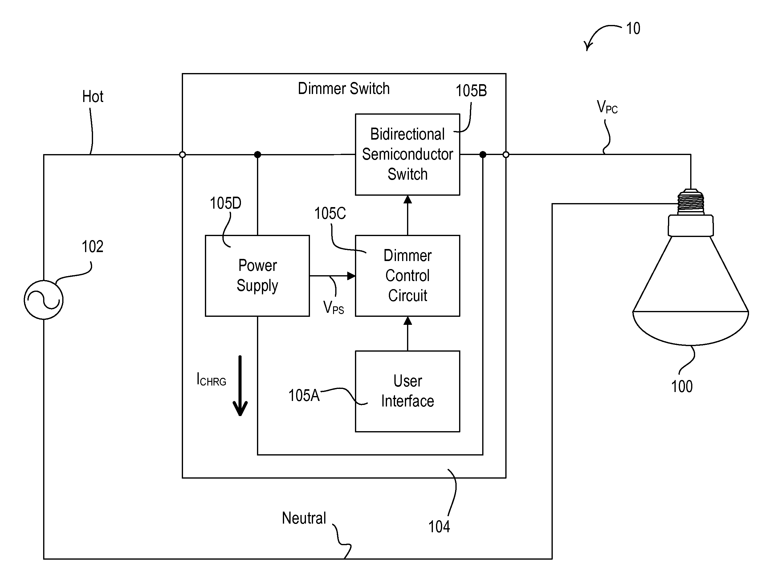
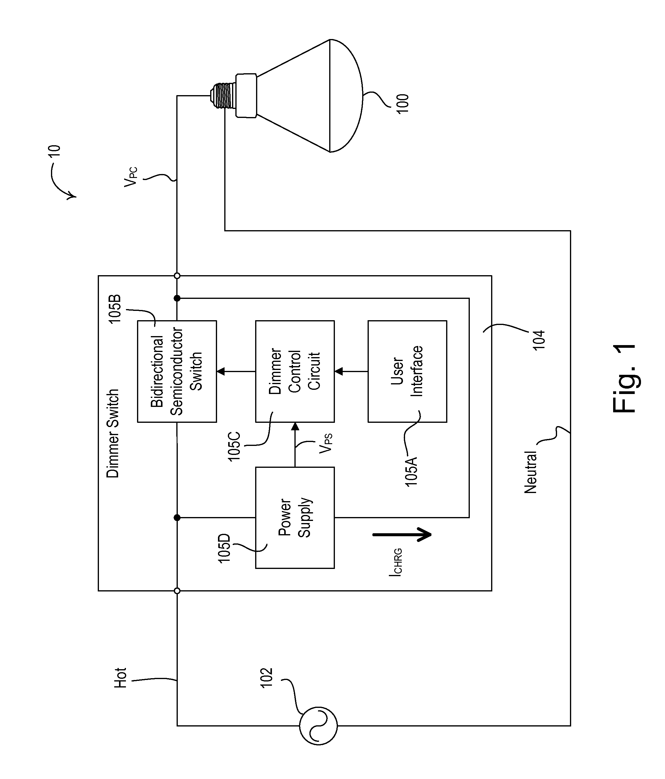
[0027]FIG. 1 is a simplified block diagram of a lighting control system 10 including a hybrid light source 100 according to an embodiment of the present invention. The hybrid light source 100 is coupled to the hot side of an alternating-current (AC) power source 102 (e.g., 120 VAC, 60 Hz) through a conventional two-wire dimmer switch 104 and is directly coupled to the neutral side of the AC power source. The dimmer switch 104 comprises a user interface 105A including an intensit...


PUM


Abstract

A method of striking a gas discharge lamp involves the steps of generating a high-frequency square-wave voltage having an operating frequency, generating a sinusoidal voltage from the high-frequency square-wave voltage, controlling the operating frequency to a low-end frequency, and increasing the amplitude of the sinusoidal voltage during successive pulse times and then decreasing the amplitude of the sinusoidal voltage towards the low-end amplitude at the end of each of the successive pulse times until the lamp has struck, where the length of each of the successive pulse times being greater than the length of the previous pulse time. A maximum amplitude of the sinusoidal voltage during each pulse time may be greater than a maximum amplitude of the sinusoidal voltage during the previous pulse time.

Description

CROSS-REFERENCE TO RELATED APPLICATIONS[0001]This application is a non-provisional application of commonly-assigned U.S. Provisional Application Ser. No. 61 / 321,289, filed Apr. 6, 2010, entitled METHOD OF STRIKING A LAMP IN AN ELECTRONIC DIMMING BALLAST, the entire disclosure of which is hereby incorporated by reference.BACKGROUND OF THE INVENTION[0002]1. Field of the Invention[0003]The present invention relates to electronic ballasts for controlling a gas discharge lamp, such as a fluorescent lamp, and more specifically, to a method of striking the gas discharge lamp.[0004]2. Description of the Related Art[0005]In order to reduce energy consumption of artificial illumination sources, the use of high-efficiency light sources is increasing, while the use of low-efficiency light sources (i.e., incandescent lamps, halogen lamps, and other low-efficacy light sources) is decreasing. High-efficiency light sources may comprise, for example, gas discharge lamps (such as compact fluorescent ...

Claims


Application Information

Patent Timeline
Patent Type & Authority Applications(United States)
IPC IPC(8): H05B35/00H05B41/36
CPCH05B35/00H05B41/295Y02B20/204H05B41/382H05B41/2985Y02B20/00
Inventor TAIPALE, MARK S.DOBBINS, AARONOZBEK, MEHMET
Owner LUTRON TECH CO LLC
Why Eureka
Try Eureka