Image processor

Active Publication Date: 2011-11-03
PANASONIC CORP
View PDF7 Cites 39 Cited by
  • Summary
  • Abstract
  • Description
  • Claims
  • Application Information

AI Technical Summary

Benefits of technology

[0034]A program according to the present invention is executed by an apparatus that includes: a polarized light source for irradiating the surface of an object with polarized light that is linearly polarized light, of which the polarization plane changes sequentially; and a camera that has an image capturing plane, on which a number of photosensitive cells, each having a size corresponding to one pixel, are arranged, and that captures an intensity image of the object's surface based on the light that has been reflected from the object's surface. The program is defined to make the apparatus perform the steps of: irradiating the object's surface with the polarized light that is linearly polarized light, of which the polarization plane changes sequentially; capturing the intensity image of the object's surface based on the l

Problems solved by technology

In other words, such an image cannot be captured just by attachin

Method used


Image

  • Image processor
  • Image processor
  • Image processor

Examples


embodiment 1

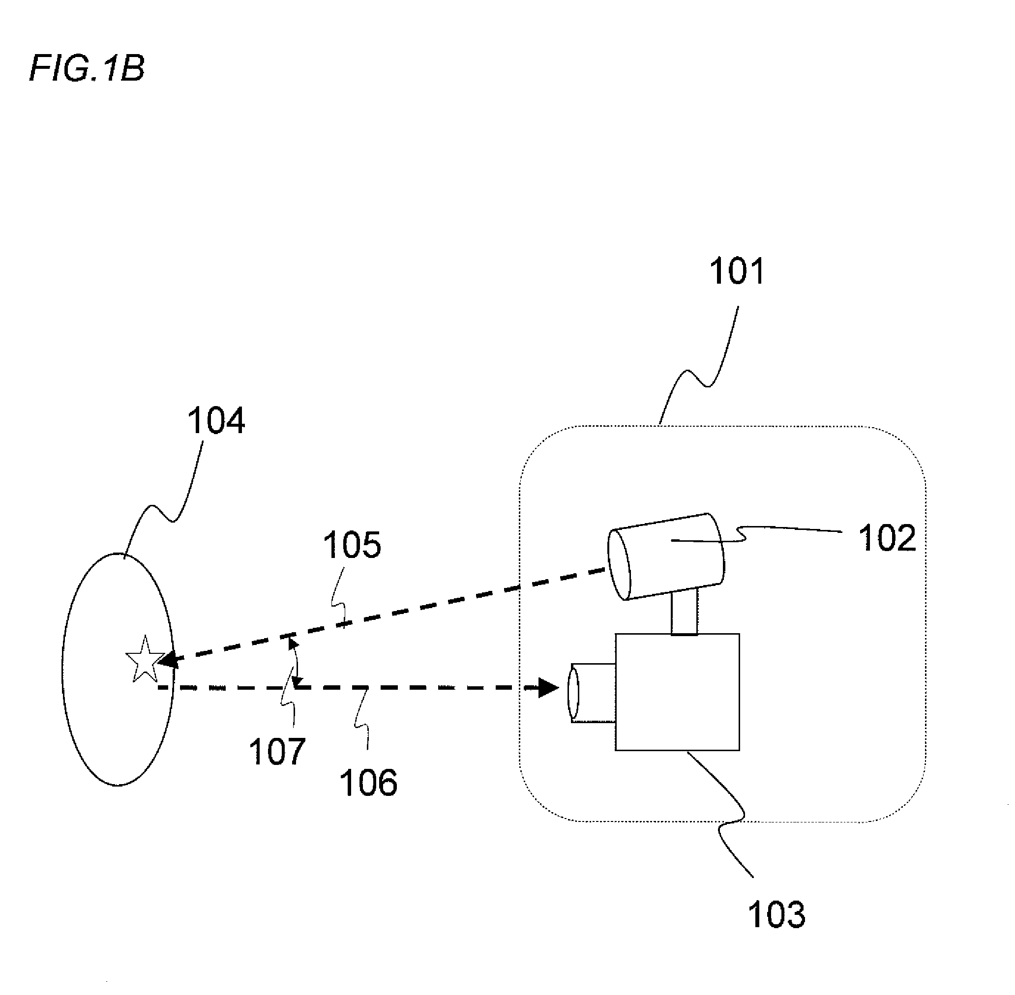
[0091]FIG. 1b Schematically Illustrates an Overall arrangement for an image processor as a first specific preferred embodiment of the present invention.

[0092]The image processor 101 of this preferred embodiment with a flexible zoom function includes a polarized light source 102 and a polarization camera 103. The object 104 being shot is irradiated with polarized light 105 by the polarized light source 102. The polarized light 105 is reflected from the surface of the object 104 (to be polarized reflected light 106) to reach the polarization camera 103, thereby recording polarization information in the polarization camera 103. As will be described later, the polarization camera 103 can obtain both an intensity image and polarization information of the object 104.

[0093]In this case, the angle LV 107 defined between the polarized light 105 and the polarized reflected light 106 is preferably 10 degrees or less. By setting the angle LV 107 to be such a small value, information about the m...

embodiment 2

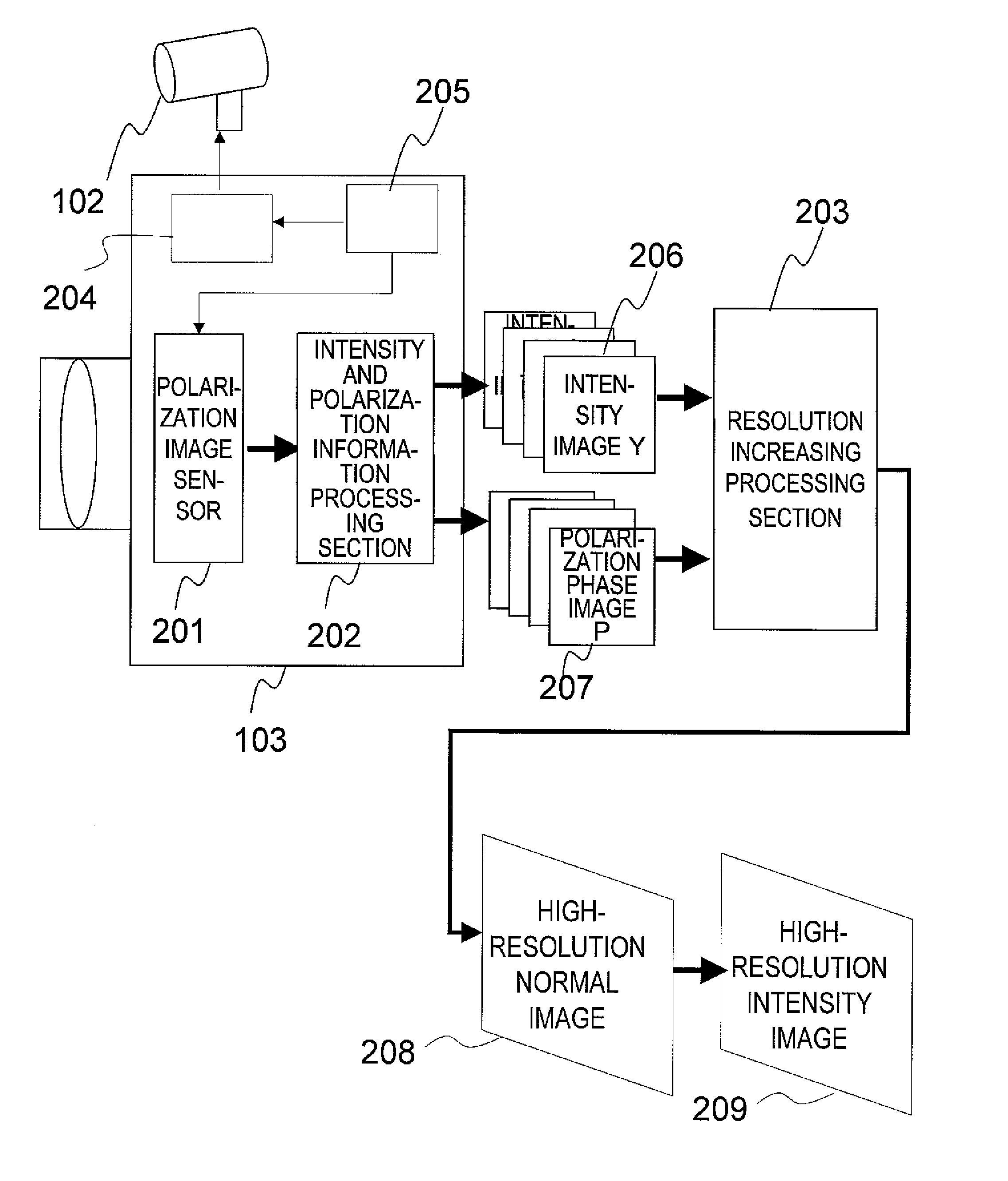
[0220]According to the first preferred embodiment of the present invention described above, the resolution is increased using polarized light and a polarization camera. However, the polarization camera has a specially designed structure with patterned polarizers, and therefore, is expensive. On top of that, the polarizer of the camera decreases not only the quantity of the incoming light that can be used but also the sensitivity as well, thus possibly debasing the eventual image quality. To overcome such a problem, according to this second preferred embodiment of the present invention, polarized light, of which the polarization plane rotates, is also used as in the first preferred embodiment described above but a normal intensity measuring camera is used to capture an image, thereby realizing the flexible zooming.

[0221]FIG. 32 illustrates this second preferred embodiment of the present invention. The only difference between the arrangement of this preferred embodiment and the one sh...

embodiment 3

[0229]Hereinafter, an image processor that can shoot both a moving picture and a still picture while changing its modes of operation will be described as a third preferred embodiment of the present invention. The basic configuration of this third preferred embodiment may be either the first or second preferred embodiment of the present invention described above. In the following description, the second preferred embodiment is supposed to be used as the basic configuration.

[0230]Generally speaking, when a moving picture is shot or reproduced, a person's sensitivity to the resolution somewhat decreases, and therefore, cannot sense the effect of the increased resolution so easily. On the other hand, when a still picture is shot or reproduced, the effect of the increased resolution is easily sensible. Particularly, in the field of medical endoscope camera, the doctor usually shoots and monitors a moving picture in inspecting his or her patient but often takes a still picture of the pati...


PUM


Abstract

An image processor (101) according to a preferred embodiment of the present invention includes a polarized light source (102) and a polarization camera (103). In shooting an object (104), the object is irradiated with polarized light (105) that rotates its polarization plane. The polarized light is reflected from the object's surface and the polarized reflected light (106) reaches the polarization camera (103), thereby recording an image there. The polarization camera (103) includes a polarization image sensor (201), an intensity and polarization information processing section (202), a polarization plane control section (204), and an image capturing control section (205). By capturing an image every time the polarization plane control section (204) changes the polarization state of the polarized light, an intensity image Y and a polarization phase image P are obtained in association with each polarization state. Using these images, a resolution increasing processing section (203) generates a high-resolution normal image (208) and a high resolution intensity image (209).

Description

[0001]This is a continuation of International Application No. PCT / JP2010 / 006346, with an international filing date of Oct. 27, 2010, which claims priority of Japanese Patent Application No. 2009-278557, filed on Dec. 8, 2009, the contents of which are hereby incorporated by reference.BACKGROUND OF THE INVENTION[0002]1. Field of the Invention[0003]The present invention relates to an image processor that has a flexible zoom function for generating an image, of which the resolution is higher than that of a single pixel of the original image that can be captured with an image sensor.[0004]2. Description of the Related Art[0005]With remarkable development of digital video equipment, the image sensors of most consumer digital still cameras now have a resolution of 1 megapixels. As a result, as far as still pictures are concerned, a resolution that is high enough to print them as beautiful photos has already been achieved. In the following applications, however, the resolution should be fu...

Claims


Application Information

Patent Timeline
IPC IPC(8): H04N5/262H04N5/225
CPCG06T1/00H04N5/238H04N5/23229H04N5/2256H04N23/56H04N23/80H04N23/75
Inventor KANAMORI, KATSUHIRO
Owner PANASONIC CORP
Why Eureka
Try Eureka