Pan-tilt apparatus

Inactive Publication Date: 2011-11-03
ROBOMEC
View PDF4 Cites 34 Cited by
  • Summary
  • Abstract
  • Description
  • Claims
  • Application Information

AI Technical Summary

Benefits of technology

[0008]The present invention is conceived to outperform the problems found in the conventional art and thus, provides a pan-tilt apparatus for a surveillance camera that enables a camera to perform a tilting motion by means of a

Problems solved by technology

Currently, due to increase in the number of vehicles, roads are being more congested.
Therefore, in a region where the traffic is flowing smoothly, many drivers are driving fast, which results in increasing car accidents.
However, in the conventional pan-tilt apparatus, a housing

Method used


Image

  • Pan-tilt apparatus
  • Pan-tilt apparatus
  • Pan-tilt apparatus

Examples


Embodiment Construction

[0045]Reference will now be made in detail to exemplary embodiments of the present invention, examples of which are illustrated in the accompanying drawings, wherein like reference numerals refer to the like elements throughout. Exemplary embodiments are described below to explain the present invention by referring to the figures.

[0046]Hereinafter, a pan-tilt apparatus for a surveillance camera according to embodiments of the present invention will be described with reference to the accompanying drawings.

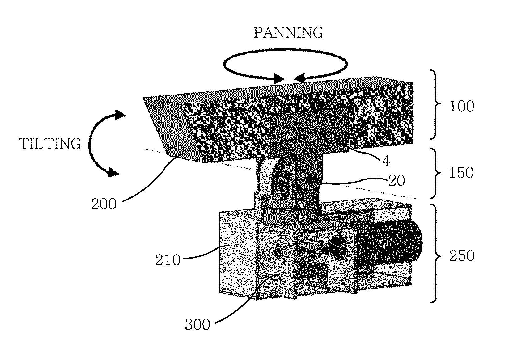
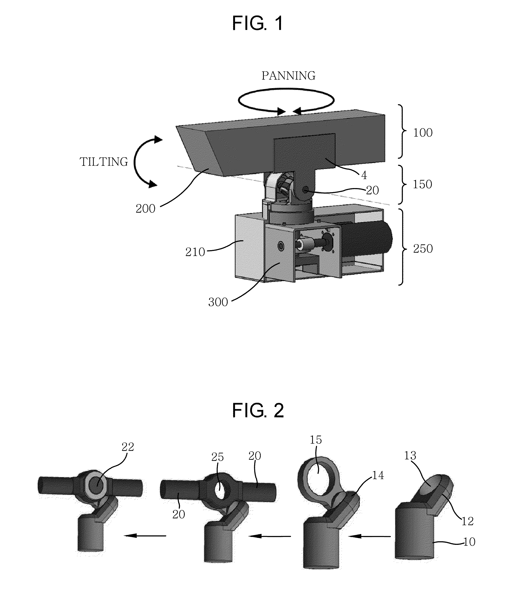
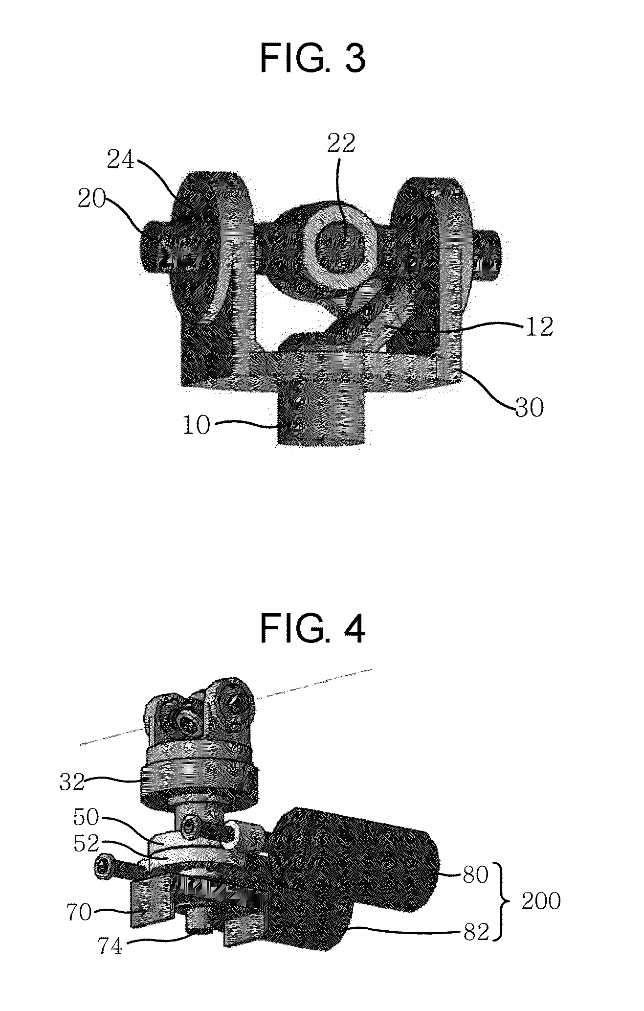
[0047]A pan-tilt apparatus for a surveillance camera according to an embodiment of the present invention may include: an image capturing unit 100 including a camera 2 and a camera holder 4 for supporting the camera 2; a motion converter 150 including a driving shaft 10, a shaft 20 being connected to a connector 14 that is inserted into the driving shaft 10, a base member 30 being inserted into one side of the driving shaft 10 and of which both ends are inserted into the shaft 20 by ...


PUM


Abstract

Provided is a pan-tilt apparatus for a surveillance camera, including an image capturing unit 100 including a camera 2 and a camera holder 4 for supporting the camera 2; a motion converter 150 including a driving shaft 10, a shaft 20 connected to a connector 14 inserted into the driving shaft 10, a base member 30 inserted into one side of the driving shaft 10 and of which both ends are inserted in the shaft 20 by including a bearing 24, a bearing 32 installed in a lower portion of the base member 30 to smoothen an operation of the base member 30, and first and second worms 50 and 52 inserted into the base member 30 and mutually connected with first and second worm gears 40 and 42 to rotate; and a driving unit 250 including first and second motors 80 and 82 being connected to first and second motor shafts 60 and 62 to be inserted into the first and second worm gears 40 and 42.

Description

CROSS-REFERENCE TO RELATED APPLICATION[0001]This application claims the benefit of Korean Patent Application No. 10-2009-0002343, filed on Jan. 12, 2009; and Korean Patent Application No. 10-2010-0001953, filed on Jan. 8, 2010 in the Korean Intellectual Property Office, the disclosure of which is incorporated herein by reference.BACKGROUND OF THE INVENTION[0002]1. Field of the Invention[0003]The present invention relates to a pan-tilt apparatus, and more particularly, to a pan-tilt apparatus that enables a camera to perform a tilting motion by means of a joint apparatus for converting a rotary motion of a motor to a reciprocal rotary motion and enables a target to perform a panning motion by employing a rotary motion of another motor using a belt or a gear.[0004]2. Description of the Related Art[0005]Currently, due to increase in the number of vehicles, roads are being more congested. Therefore, in a region where the traffic is flowing smoothly, many drivers are driving fast, which ...

Claims


Application Information

Patent Timeline
IPC IPC(8): G03B17/00F16M13/00
CPCH04N7/185H04N5/232H04N23/50H04N23/695H04N7/18
Inventor YIM, JIN WHANKWON, TAE HOONHAN, GYU BONG
Owner ROBOMEC
Why Eureka
Try Eureka