System for securing a device using two din rails

a technology of securing devices and din rails, which is applied in the direction of connecting devices, electrical equipment, connections, etc., can solve the problems of inability to support or design relatively heavy/large devices, inherently less flexible and difficult to service, and not only time-consuming to us

Inactive Publication Date: 2011-11-03
ROCKWELL AUTOMATION TECH
View PDF5 Cites 23 Cited by
  • Summary
  • Abstract
  • Description
  • Claims
  • Application Information

AI Technical Summary

Problems solved by technology

However, such DIN rails have limited load and moment bearing capacity and are not designed for or able to support relatively heavy / large devices.
The resulting system is, however, inherently less flexible and more difficult to service should there be a need to remove the devices.
However, such techniques are not only time consuming to use, but may also result in inaccurate alignment / positioning of the device along with the DIN rails, leading to additional time and effort to correct any alignment errors that make the devices insecure or prone to detachment from the rails.

Method used


Image

  • System for securing a device using two din rails
  • System for securing a device using two din rails
  • System for securing a device using two din rails

Examples


Embodiment Construction

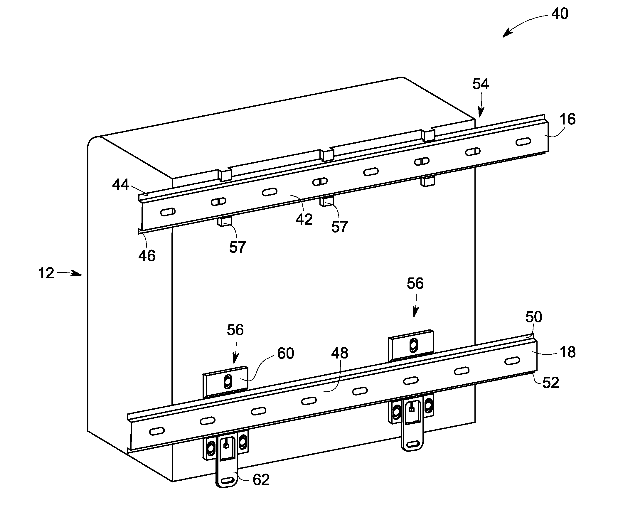
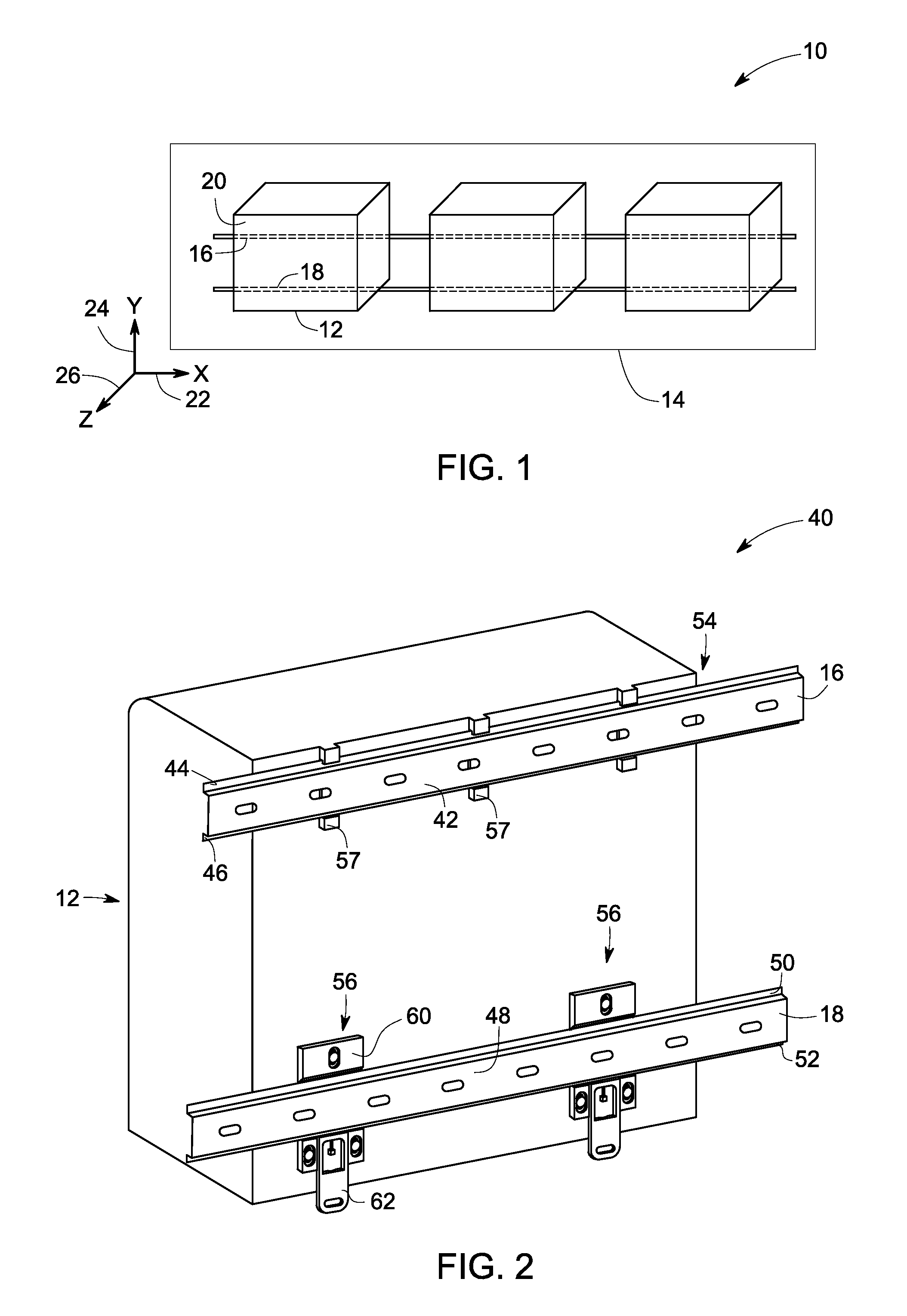
[0020]As discussed in detail below, embodiments of the present technique function to provide a system for securing large devices using two DIN rails. As used herein, the term “DIN rail” refers to a standardized metal rail having a hat-shaped cross-section and is characterized by an elongated channel having opposed coplanar flanges along its length.

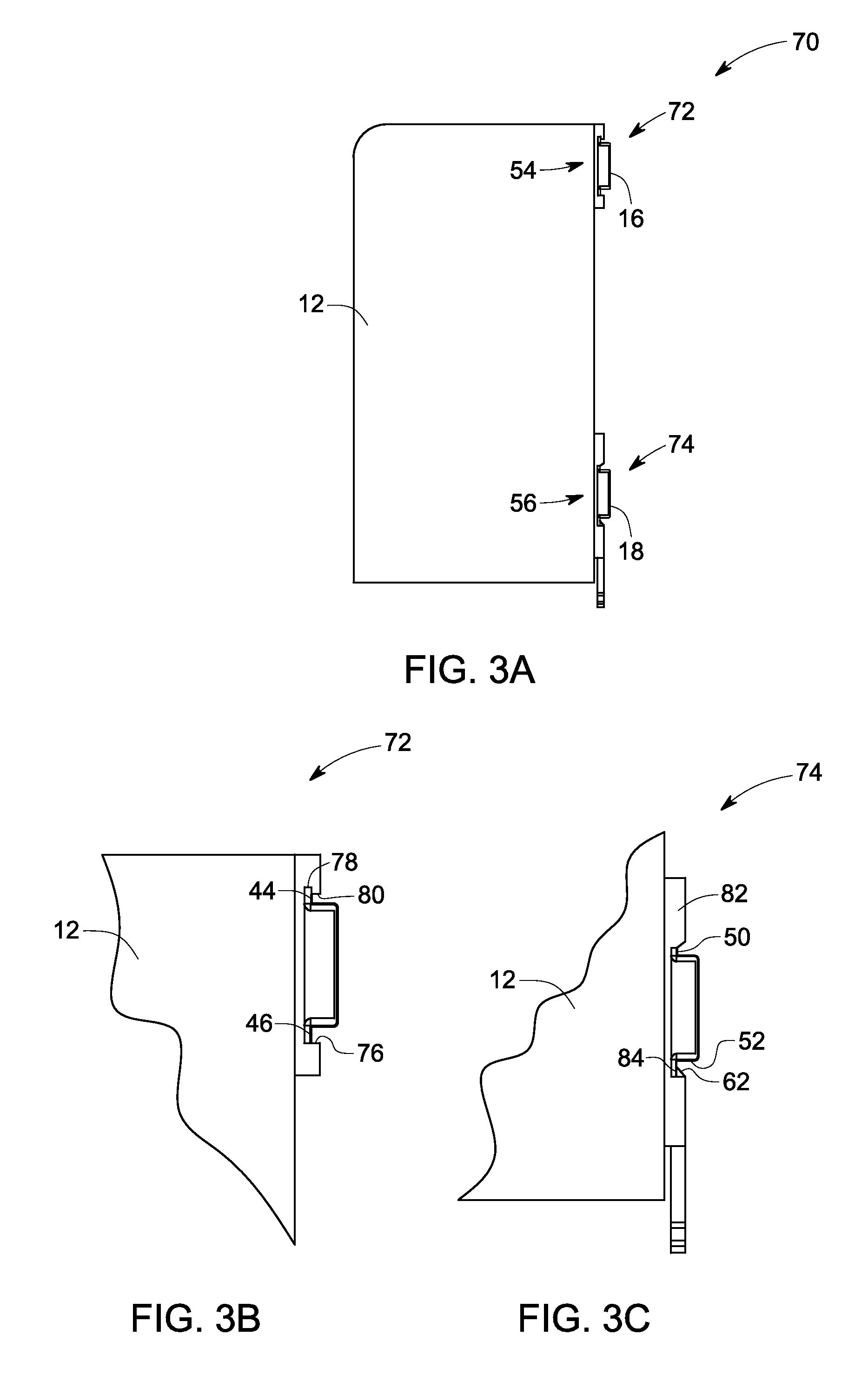
[0021]Such DIN rails are known in the art for mounting electrical components in panels and are available in standard widths (e.g., 35 mm, 15 mm etc). In particular, the present technique utilizes two horizontal DIN rails for mounting at least one device such as industrial control equipment to a panel inside an equipment rack. Furthermore, static and movable attachment structures are employed to secure the at least one device to the DIN rails.

[0022]References in the specification to “one embodiment”, “an embodiment”, “an exemplary embodiment”, indicate that the embodiment described may include a particular feature, structure, or characteris...


PUM


Abstract

A system for securing a device to first and second DIN rails is provided. The system includes a static attachment structure configured to secure the device to the first DIN rail and a movable attachment structure configured to secure the device to the second DIN rail. The movable attachment structure includes a carrier secured to the device and a latch secured to the carrier and configured to engage the device to the second DIN rail in a latched position.

Description

BACKGROUND[0001]The invention relates generally to rail mounted devices, and particularly to a system for securing devices using two rails.[0002]Various systems are known and are in use for mounting devices on panels and in enclosures. One way of mounting such devices is through the use of rails that have inwardly or outwardly projecting flanges along their length for receiving the devices such as terminal strips, input / output modules, small motor drives, circuit breakers and so forth within systems such as employed for industrial control applications. Such rails are commonly referred to as “DIN” rails (a name derived from the acronym for Deutsches Institute fur Normung, a German standards-setting organization), and have become a quasi-standard in many industrial and other settings. Such DIN rails are typically attached to a panel wall via tapped holes, which do not require precision positioning. The devices, in turn, are required to have features that mate to the DIN rail profile.[...

Claims


Application Information

Patent Timeline
Patent Type & Authority Applications(United States)
IPC IPC(8): H01R13/60
CPCH05K7/1474
Inventor BARAN, MICHAEL S.
Owner ROCKWELL AUTOMATION TECH
Why Eureka
Try Eureka