
Method for determining an insertion trajectory of a tool in a deformable tissular matrix and robotic system executing the method

Active Publication Date: 2011-11-03
CENT NAT DE LA RECHERCHE SCI +2
View PDF6 Cites 12 Cited by
  • Summary
  • Abstract
  • Description
  • Claims
  • Application Information

AI Technical Summary

Benefits of technology

An advantage of this method is that it enables accurately reaching a target object moving within a tissular matrix without touching the obstacles. This method helps minimize the risks of failure and medical complication.
Another advantage is that the patient does not need to be repositioned, should his position correspond to a position outside an intervention window of the prior art. Indeed, the present method enables reaching the target object along multiple trajectories having varied orientations.

Problems solved by technology

Indeed, chances of success for intervention depend on this determination, since incorrect or insufficiently accurate determination can result in failure in the attempt to reach the target object, or can even cause complications potentially serious for the health of the patient due to damage to some tissue or organs as the tool is moving through the tissular matrix.
However, this method does not take into account deformation of the tissular matrix into which the tool is inserted.
Yet, deformation of the tissular matrix causes displacement of the target object.
Therefore, even though the trajectory has been optimized by this method, it is still possible to miss the target object or touch other tissue.
However, this method cannot be applied to determining an insertion trajectory to reach a single target object.
Yet, there is no single solution when there is only a single target object.

Method used


Image

  • Method for determining an insertion trajectory of a tool in a deformable tissular matrix and robotic system executing the method
  • Method for determining an insertion trajectory of a tool in a deformable tissular matrix and robotic system executing the method
  • Method for determining an insertion trajectory of a tool in a deformable tissular matrix and robotic system executing the method

Examples


Embodiment Construction

Throughout the description, the term trajectory means a set of parameters for defining the path of a tool to be inserted into a tissular matrix. These parameters can vary and depend on the system of coordinates used.

By way of example, a trajectory can be defined, in a previously selected reference frame, by the coordinates of an insertion point of the tool in the tissular matrix and the coordinates of a point of arrival of the tool in the tissular matrix after its insertion. The trajectory may further be defined by the coordinates of an insertion point of the tool, two angles with respect to the axes of the previously selected reference frame, and an insertion length.

In these two examples, these parameters are sufficient for a rectilinear trajectory, whereas for a curved trajectory, a radius of curvature can complete these parameters.

The determination of a trajectory is therefore understood by determination of these parameters.

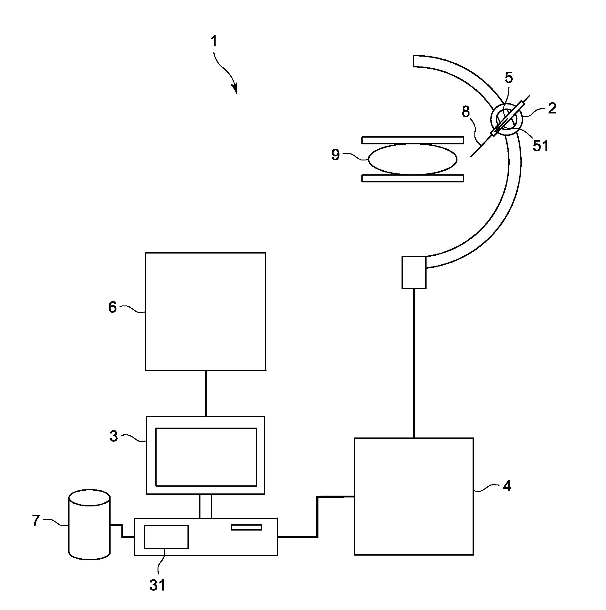
FIG. 8 schematically illustrates a medical imaging modul...


PUM


Abstract

A method for determining an insertion trajectory of a tool for reaching a moving target object prior to its insertion into a tissular matrix is provided, the method comprising: acquiring images of the tissular matrix; constructing a three-dimensional representation of the tissular matrix; determining coordinates of the initial position of the target object and of the obstacles; determining at least one potential trajectory of the tool from the coordinates of the obstacles of the tissular matrix and of the initial position of the target object; simulating insertion of the tool in the tissular matrix to determine displacement of the target object within the tissular matrix during insertion of the tool up to the initial position of the target object along the potential trajectory; determining a new position of the target object based on the determined displacement; and determining the insertion trajectory for the new position of the target object.

Description

BACKGROUND OF THE INVENTION1. Field of the InventionThe field of the invention generally relates to medical imaging and more particularly relates to methods for determining an insertion trajectory of a tool for reaching a target object, prior to its insertion into a tissular matrix, moving within the tissular matrix, from image acquisition suitable for producing a three-dimensional representation of the tissular matrix.The field of the invention also relates to the field of robotic systems for positioning a tool for reaching a target object, prior to its insertion into a tissular matrix, within the tissular matrix, from a determination of an insertion trajectory.2. Description of the Prior ArtDetermining an insertion trajectory of a tool for reaching a target object to be inserted into a tissular matrix within the tissular matrix is important in the medical field.Indeed, chances of success for intervention depend on this determination, since incorrect or insufficiently accurate dete...

Claims


Application Information

Patent Timeline
IPC IPC(8): A61B19/00G06G7/48
CPCA61B10/02A61B19/50A61B2019/507A61B2017/00716A61B19/5244A61B34/20A61B2034/107A61B34/10
Inventor VANCAMBERG, LAURENCESAHBANI, ANISMULLER, SERGEMOREL, GUILLAUME
Owner CENT NAT DE LA RECHERCHE SCI
Features
  • Generate Ideas
  • Intellectual Property
  • Life Sciences
  • Materials
  • Tech Scout
  • Unparalleled Data Quality
  • Higher Quality Content
  • 60% Fewer Hallucinations
Learn More