
Light irradiation device

a light irradiation and light technology, applied in the field of light irradiation devices, can solve the problems of large burden on skin, economic and temporal burden, etc., and achieve the effects of reducing skin burden, reducing hair loss, and preventing cell proliferation of hair follicles

Active Publication Date: 2011-11-03
PANASONIC CORP
View PDF2 Cites 21 Cited by
  • Summary
  • Abstract
  • Description
  • Claims
  • Application Information

AI Technical Summary

Benefits of technology

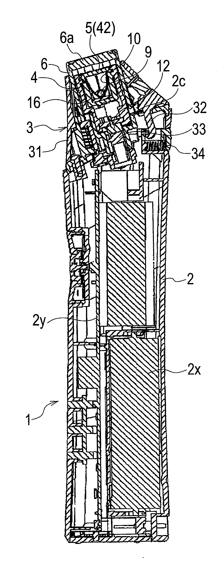
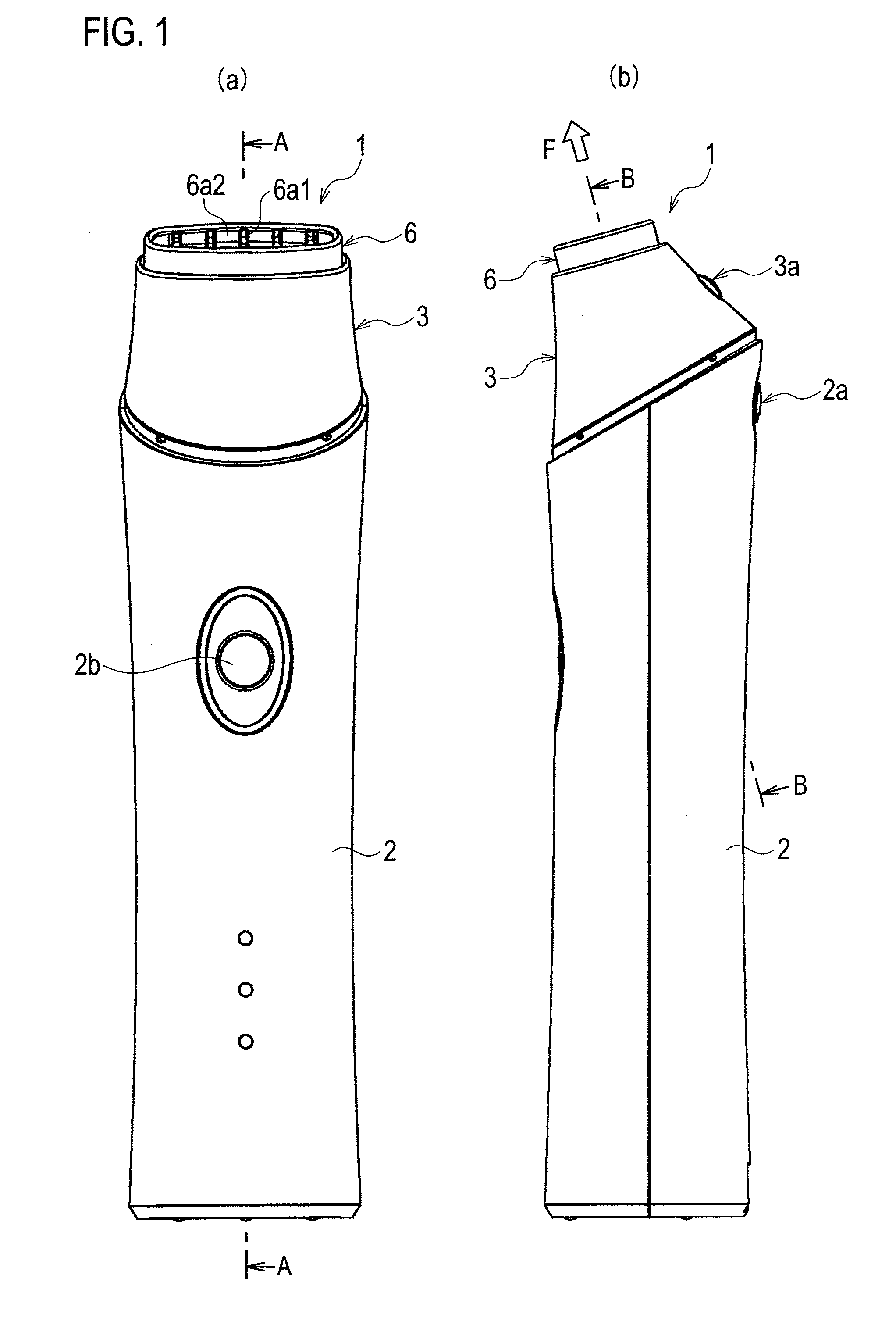
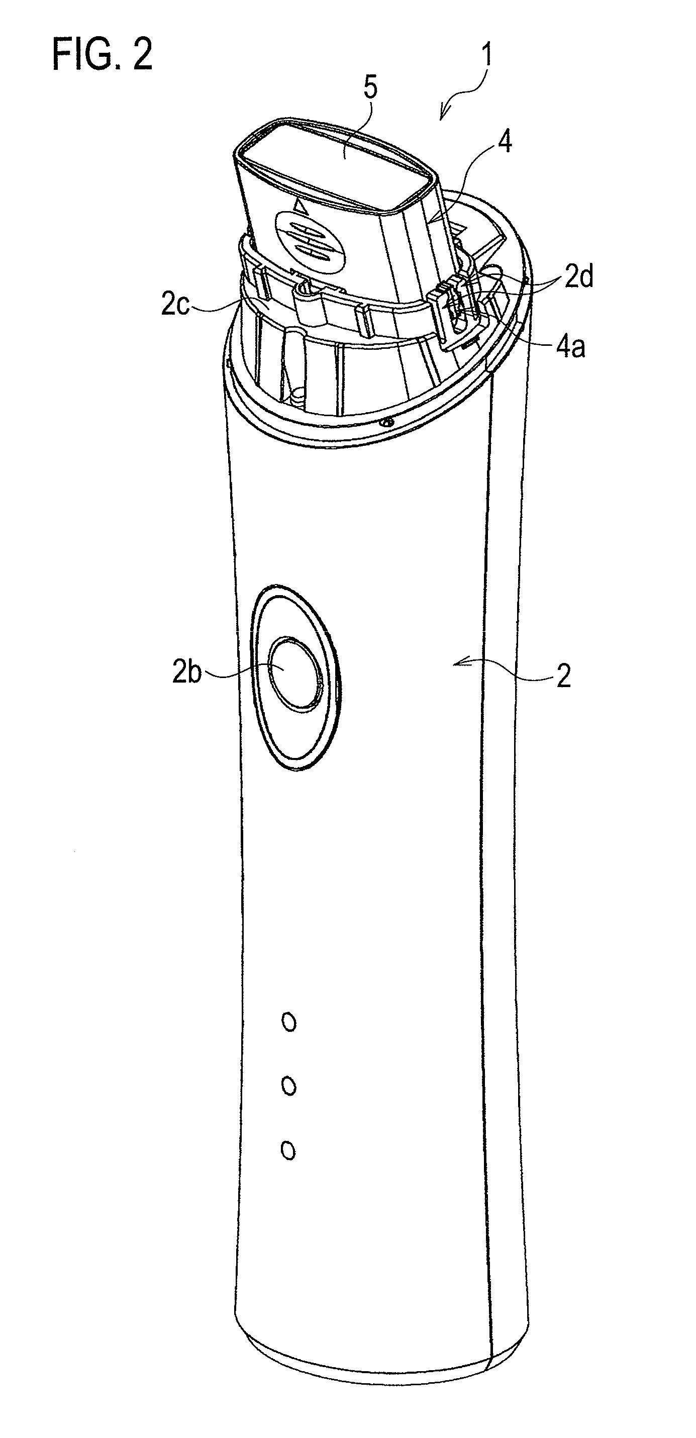
"The present invention is a light irradiation device that can be easily used at home for hair removal or reduction. The device includes a light source giving pulses of light in a wavelength range from 400 to 1200 nm and a light guide distributing the pulses of light with energy intensity of 0.2 to 10 J / cm2 at a predetermined distance from the light outgoing surface. The light guide includes a light orientation controller adjusting the pulses of light. The device can provide sufficient hair removal or reduction without causing burden on skin. It can induce cellular death without causing skin damage. The device is easy to use, economical, and can be operated at home."

Problems solved by technology

Such hair removal or reduction using laser light is accompanied with destruction of cells and tends to cause side effects such as burns or freckles, thus giving large burden to skin.
However, the operations by expert doctors cause economical and temporal burdens.

Method used


Image

  • Light irradiation device
  • Light irradiation device
  • Light irradiation device

Examples


example 1

[0057]The back skins of C57BL / 6 mice with follicles being in the telogen phase not in the anagen phase were subjected to waxing hair removal to induce the anagen phase of hair. Irradiation was started five days after the hair removal. The irradiation condition was that 400 to 1200 nm wavelength light was distributed as pulses of a full width at half maximum of 600 μs so as to have energy intensity of 0.2 to 0.25 J / cm2 at a distance of 5 mm from the front surface of the lens 5. The capacity of the main capacitor was set to 400 pF at this time. The irradiation was continuously performed for an area of 1×3 cm five times a day. The irradiated mice were observed over time, or the skins thereof were sampled. The skin sampling was performed within 2 hours, 12 hours, one day, three days, and seven days after the irradiation. At the sampling, in order to cause BrdU to enter growing cells, BrdU (100 μg / g bodyweight) was injected into abdominal cavities one hour before the sampling.

[0058]1. Ce...

example 2

[0080]Next, the circuit design was changed to set the capacitance of the main capacitor to 800 μF, which was twice that of Example 1. Moreover, a long pass filter (0G570, SCHOTT) was provided at the front of the lens. The intensity of emitted light was doubled by doubling the capacitance of the capacitor, and the short-wavelength components were cut off by the filter. Accordingly, 550 to 1200 nm wavelength light was distributed as pulses having a full width at half maximum of 1200 μs so as to have energy intensity of 0.2 to 0.3 7 / cm2 at a distance of 5 mm from the front surface of the lens.

[0081]FIG. 18(a) illustrates an irradiation spectrum 18A of Example 1, an irradiation spectrum 18B of Example 2, and melanin absorptance 18C. In the irradiation spectrum 18B of Example 2, wavelengths of 550 nm or shorter were cut off. Moreover, by doubling the capacitance of the capacitor, the irradiation energy was substantially doubled at a wavelength of 640 nm, for example.

[0082]Next, FIG. 18(b...


PUM


Abstract

To provide a light irradiation device capable of easily removing and reducing hair with low power light without burden on skin. The light irradiation device according to the present invention includes a light source giving pulses of light in a wavelength range from 400 to 1200 nm and a light guide distributing the pulses of light given from the light source with energy intensity of 0.2 to 10 J / cm2 at a predetermined distance from the light outgoing surface.

Description

TECHNICAL FIELD[0001]The present invention relates to a light irradiation device performing light irradiation for hair removal or reduction.BACKGROUND ART[0002]In the medical field, hair removal or reduction by light irradiation is known. Hair is removed or reduced by irradiating skin with high power laser light (class 4) to cause necrosis of cells of hair roots and follicles. Such hair removal or reduction using laser light is accompanied with destruction of cells and tends to cause side effects such as burns or freckles, thus giving large burden to skin. The operations are therefore conducted by expert doctors. However, the operations by expert doctors cause economical and temporal burdens. Accordingly, there are demands for hair removal or reduction equipment capable of being easily used at home. For example, JP 2005-211689 A discloses a home hair removal device projecting low power light.CITATION LISTPatent Literature[0003]Patent Literature 1: JP 2005-211689 ASUMMARY OF INVENTIO...

Claims


Application Information

Patent Timeline
Patent Type & Authority Applications(United States)
IPC IPC(8): A61N5/06
CPCA61B18/203A61B2018/00452A61B2018/00476A61N2005/0654A61N5/0617A61N2005/0644A61B2018/1807A61N5/06A45D26/00
Inventor HAMADA, CHOSEIYAMASAKI, MASAKOMATSUZAKI, TAKASHI
Owner PANASONIC CORP
Learn More