
Fast connecting tube module

a technology of fast connection and tube module, which is applied in the direction of hose connection, water installation, construction, etc., can solve the problems of increasing the number of assembly steps, increasing the cost, and increasing the number of components, so as to achieve stable connection and low cost , the effect of simple overall structur

Inactive Publication Date: 2011-11-10
LIN MING SHUAN
View PDF1 Cites 11 Cited by
  • Summary
  • Abstract
  • Description
  • Claims
  • Application Information

AI Technical Summary

Benefits of technology

[0016]The advantage of the present invention lies in that the overall structure is simple, and thus low cost, and that the connecting tube module is stable when assembled.
lies in that the overall structure is simple, and thus low cost, and that the connecting tube module is stable when assembled.

Problems solved by technology

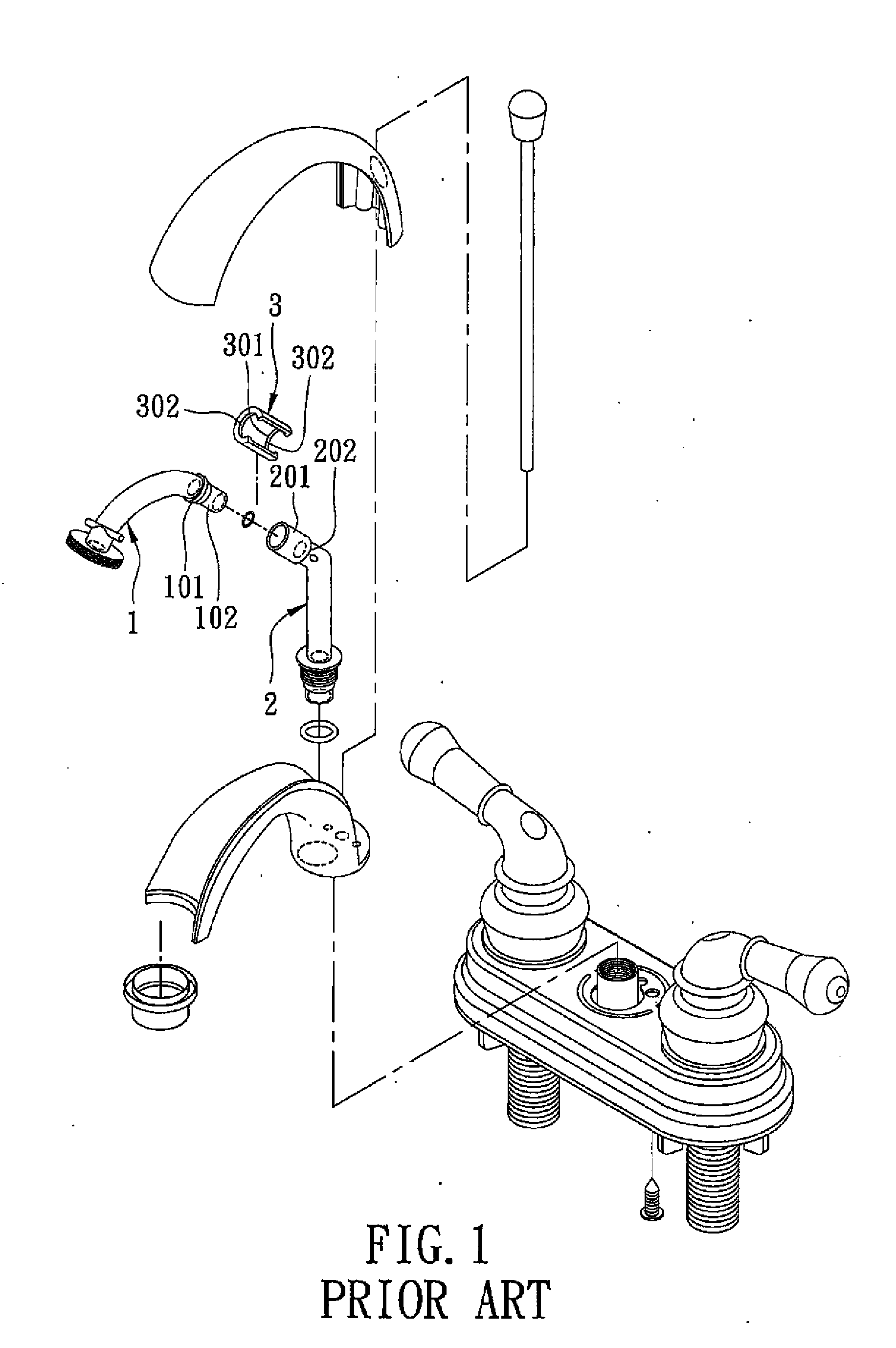
However, since the spout is curvy and difficult for mold removal, current plastic faucet spouts are often broken into several separate components that need to be assembled together for use.
1. With the provision of the lock ring 3, the number of components for the conventional faucet spout is increased, the number of assembly steps is increased, and the cost is also increased.
2. The lock ring 3 may be irreversibly deformed during expansion through the slit 301, thereby adversely affecting assembly of the first and second connecting tubes 1, 2.
3. The lock ring 3 only prevents relative movement between the first and second connecting tubes 1, 2 in the axial direction, and does not lock the first and second connecting tubes 1, 2 in the circumferential direction. Therefore, relative rotation between the first and second connecting tubes 1, 2 is possible, resulting in inconvenience during use of the conventional faucet spout.

Method used


Image

  • Fast connecting tube module
  • Fast connecting tube module
  • Fast connecting tube module

Examples


Embodiment Construction

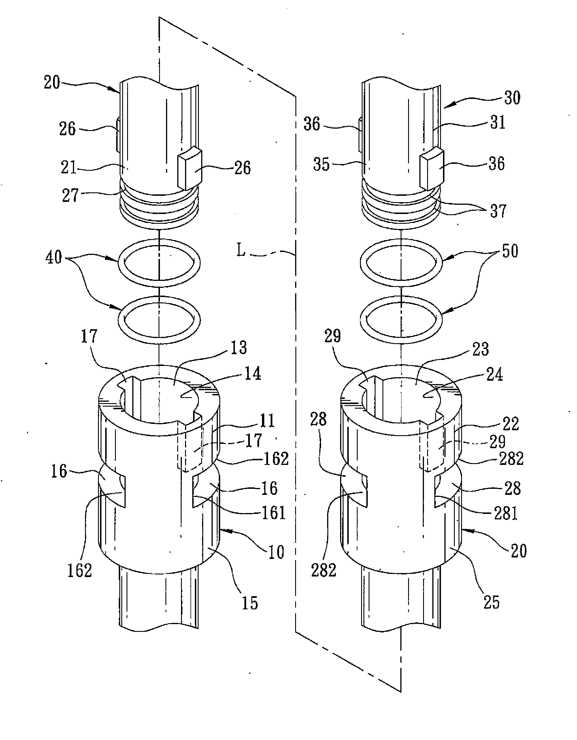
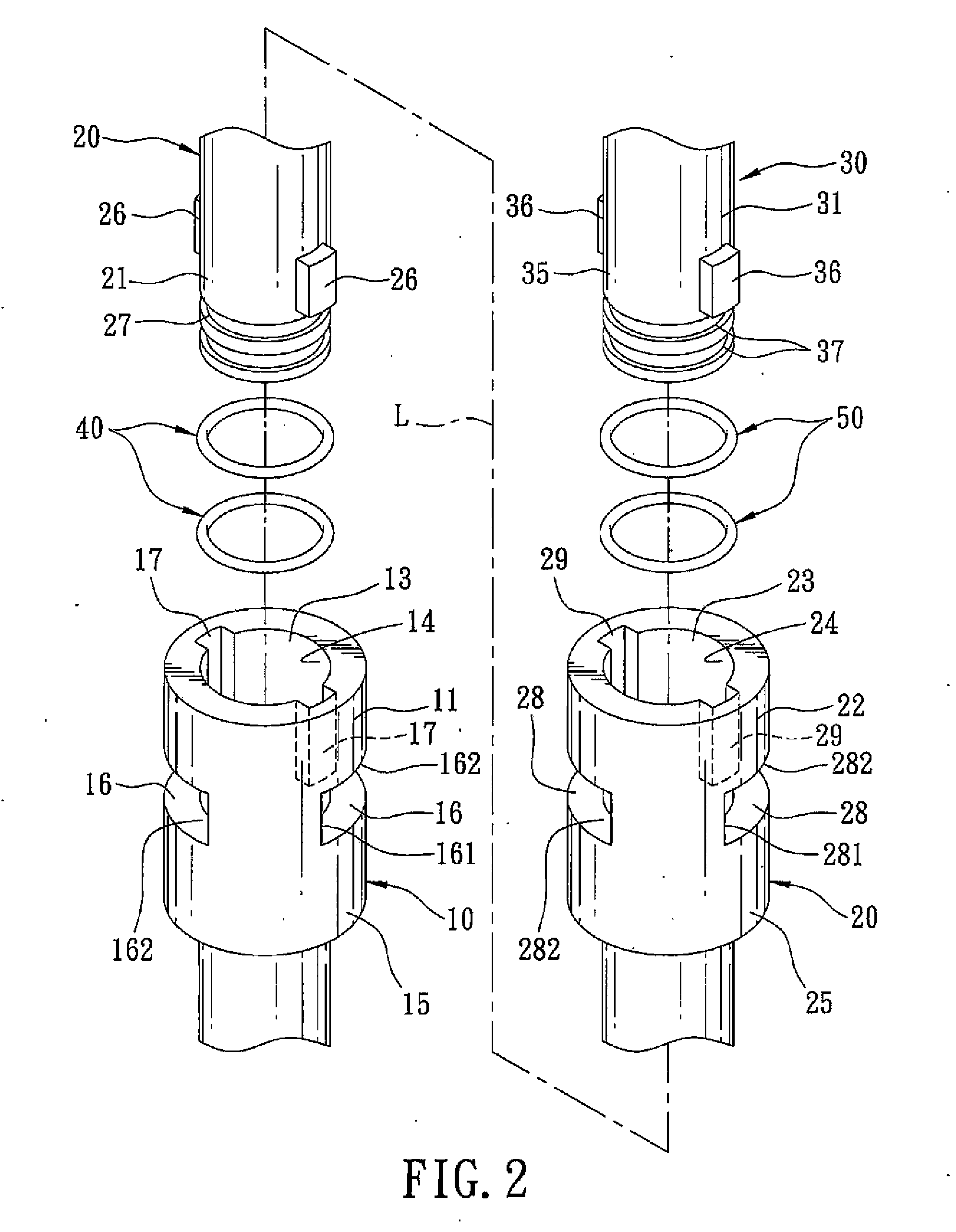
[0025]With reference to FIG. 2, FIG. 3 and FIG. 7, the preferred embodiment of a connecting tube module 100 of the present invention is illustrated to be applied to a spout of a plastic faucet. The connecting tube module 100 includes a first tube member 10, a second tube member 20, and a first leakproofing member 40.

[0026]The first tube member 10 defines a first inner space 13, and has first and second end portions 11, 12 that are opposite to each other along a tube axis (L), and a first inner wall surface 14 that defines the first inner space 13 and that extends from the first end portion 11 to the second end portion 12. The first inner wall surface 14 is formed at the first end portion 11 with a first lock groove 16 that extends in a circumferential direction and a first slide groove 17 that extends parallel to the tube axis (L) and that is in spatial communication with the first lock groove 16. The first lock groove 16 has an entrance end 161 that corresponds in location to the f...


PUM


Abstract

A connecting tube module includes first and second tube members and a leakproofing member. The first tube member has an inner wall surface that is formed with a lock groove extending in a circumferential direction, and a slide groove extending parallel to a tube axis. The lock groove has an entrance end corresponding in location to the slide groove in a direction of the tube axis and a lock end opposite to the entrance end along the circumferential direction. The second tube member has an outer wall surface provided with a protruding block. The leakproofing member is disposed between the inner wall surface and the outer wall surface. When the second tube member is inserted into the first tube member, the protruding block slides along the slide groove into the entrance end and is disposed at the lock end upon relative rotation of the first and second tube members in the circumferential direction.

Description

BACKGROUND OF THE INVENTION[0001]1. Field of the Invention[0002]The invention relates to a tube connecting mechanism, more particularly to a fast connecting tube module.[0003]2. Description of the Related Art[0004]A conventional plastic faucet spout has the advantages of being lightweight and economical. However, since the spout is curvy and difficult for mold removal, current plastic faucet spouts are often broken into several separate components that need to be assembled together for use.[0005]As shown in FIG. 1, a conventional faucet spout includes a first connecting tube 1, a second connecting tube 2 and a lock ring 3. The first connecting tube 1 has a flange 101, and a sleeve segment 102 connected to the flange 101. The second connecting tube 2 has an assembling segment 201 for insertion of the sleeve segment 102 of the first connecting tube 1 therein, and a shoulder 202 connected to the assembling segment 201. The lock ring 3 has a slit 301 resulting in a C-shaped cross-sectio...

Claims


Application Information

Patent Timeline
IPC IPC(8): F16L25/06
CPCF16L37/248E03C1/0403
Inventor LIN, MING-SHUAN
Owner LIN MING SHUAN
Learn More