
Drowning prevention system

a technology of prevention system and drowning, applied in the field of water safety, can solve the problems of tragic death, inability to fence such bodies of water, and increasing problem of accidental drowning in swimming pools and other bodies of water

Inactive Publication Date: 2011-11-10
ADAMS DONALD
View PDF7 Cites 15 Cited by
  • Summary
  • Abstract
  • Description
  • Claims
  • Application Information

AI Technical Summary

Benefits of technology

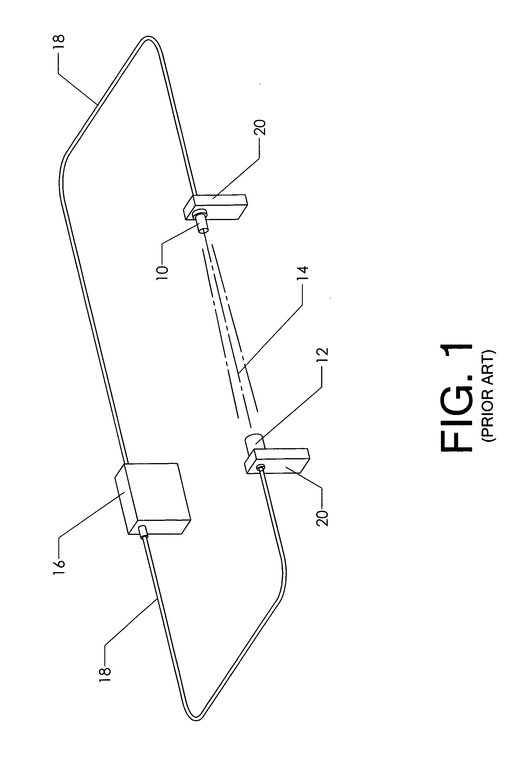
[0011]FIG. 1 is a perspective view, showing a simple

Problems solved by technology

Accidental drownings in swimming pools and other bodies of water are an increasing problem.
While such a perimeter does provide security, it is subject to human error in that gates are often left open or exterior dwelling doors leading to the pool area may be left unlatched.
A lapse of only a few minutes can unfortunately result in a tragic death.
It is impractical to fence such bodies of water.

Method used


Image

  • Drowning prevention system
  • Drowning prevention system
  • Drowning prevention system

Examples


Embodiment Construction

[0018]The inventive method can be carried out using a virtually endless variety of components and connections. FIGS. 1-7 illustrate preferred embodiments. However, the invention is by no means confined to the embodiments disclosed.

[0019]FIG. 1 illustrates a prior art detector system using a photodetector. Emitter 10 emits a focused beam of infrared light—labeled as IR beam 14 in the view. The emitter is oriented to project this beam upon detector 12. Detector 12 is configured to monitor for the presence of IR beam 14. Mounts 20 are used to maintain the desired alignment between the emitter and the detector. When the beam is “seen” by the detector, it typically sends a positive signal to controller 16 over wiring 18.

[0020]When an object interrupts the optical path, detector 12 no longer “sees” IR beam 14. An appropriate signal is sent to controller 16 which interprets the receipt of the signal as an interruption in the beam. The emitter, the detector, and the beam therebetween may be...


PUM


Abstract

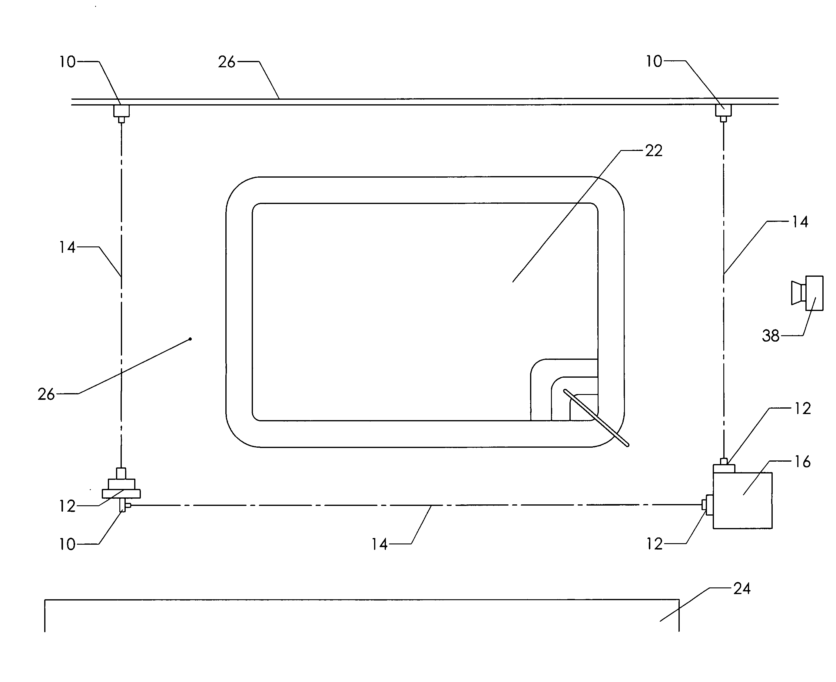
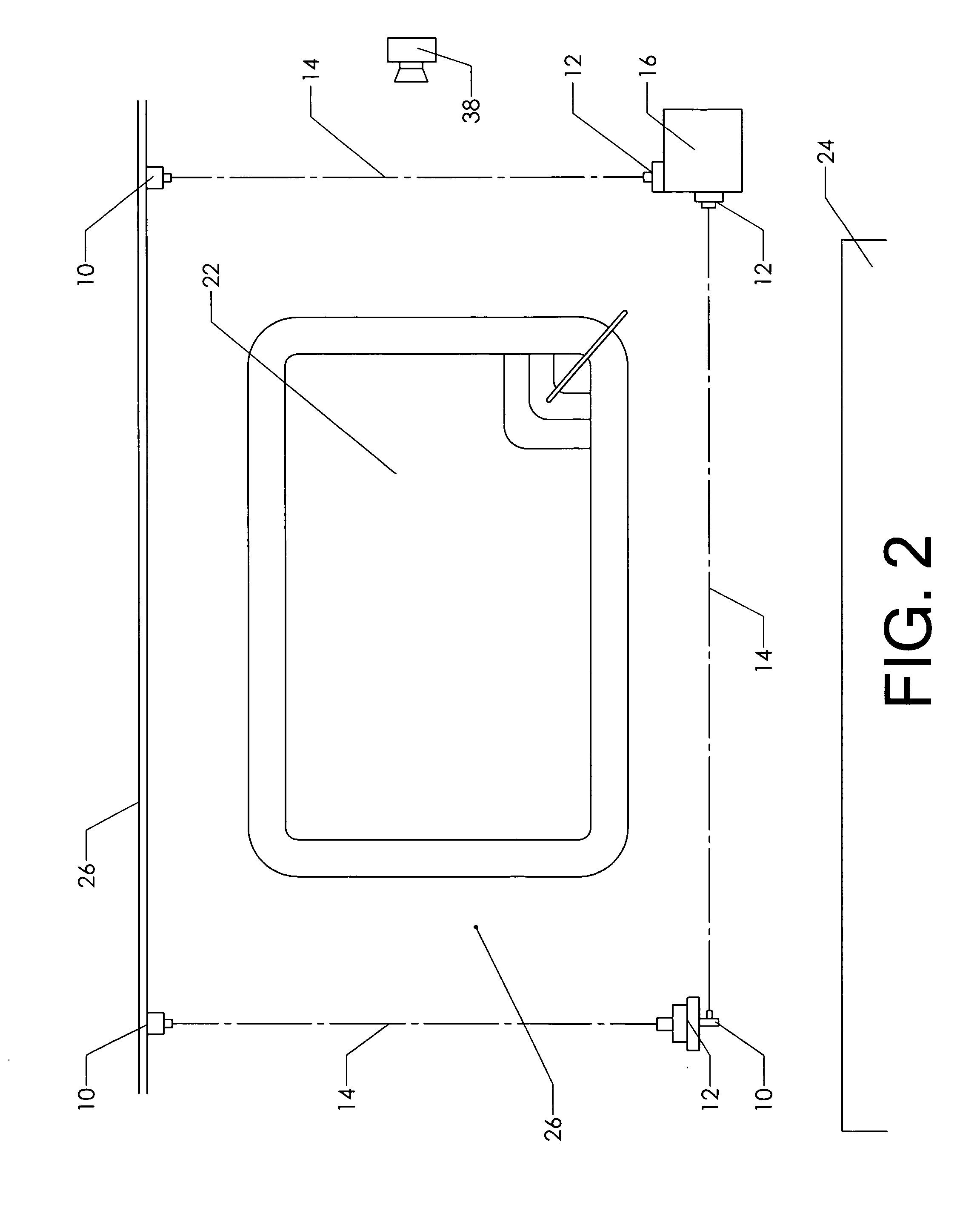
A method for providing a security barrier proximate a body of water such as a lake or a swimming pool. One or more beams—preferably infra red light beams—define the barrier. A detector is positioned to monitor each beam so that a moving object “cutting” the beam can be detected by a controller in communication with the beam or beams. A motion detector monitors for motion in a broad area around the location of the security perimeter. The motion detector is also in communication with the controller. The controller deactivates the beams and relies solely on the motion detector when no objects are near the perimeter. Once the motion detector senses an object in the area of the perimeter, however, the controller activates the beams. If an object then interrupts a beam, the controller activates an alarm.

Description

CROSS-REFERENCES TO RELATED APPLICATIONS[0001]Not applicable.STATEMENT REGARDING FEDERALLY SPONSORED RESEARCH OR DEVELOPMENT[0002]Not applicable.MICROFICHE APPENDIX[0003]Not applicableBACKGROUND OF THE INVENTION[0004]1. Field of the Invention[0005]The present invention relates generally to the field of water safety. More specifically, the invention comprises a method for electronically monitoring a boundary around a body of water and generating an alarm if the boundary is crossed.[0006]2. Description of the Related Art[0007]Accidental drownings in swimming pools and other bodies of water are an increasing problem. The drowning victims are generally toddlers, who fall into the water and drown before an adult realizes they are missing. Security around swimming pools has traditionally been provided by a fence. While such a perimeter does provide security, it is subject to human error in that gates are often left open or exterior dwelling doors leading to the pool area may be left unlat...

Claims


Application Information

Patent Timeline
IPC IPC(8): G08B19/00G01J5/00
CPCG08B13/183
Inventor ADAMS, DONALD
Owner ADAMS DONALD
Learn More