Motion vector generation apparatus and motion vector generation method

a motion vector and generation apparatus technology, applied in the field of motion vector generation apparatus and motion vector generation method, can solve the problems of increasing operation time, search is not performed, and estimation accuracy errors

Active Publication Date: 2011-11-10
KONICA MINOLTA INC
View PDF2 Cites 85 Cited by
  • Summary
  • Abstract
  • Description
  • Claims
  • Application Information

AI Technical Summary

Benefits of technology

[0017]In a motion vector generation apparatus and a motion vector generation method according to the present invention, when motion vectors are sequentially generated for a plurality of images, a target point is determined at a sub-pixel level in any of the plurality of images, a corresponding point corresponding to the target point is searched at the sub-pixel level in another image different from this image, and a motion vector is calculated on the basis of the target point and the corresponding point. Then, the corresponding point is defined as a new target point, and the aforementioned process is repeated to sequentially generate the motion vectors. Thus, the motion vector generation apparatus and the motion vector generation method according to the present invention can compute consecutive motion vectors by performing correspondence search at the sub-pixel level in the plurality of images.

Problems solved by technology

Accordingly, the method disclosed in this Patent Document 2 has a problem of errors in estimation accuracy.
In addition, creating the sub-pixel versions of the images causes a problem of increasing operation time.
However, the search is not performed with the target point defined at the sub-pixel level.

Method used


Image

  • Motion vector generation apparatus and motion vector generation method
  • Motion vector generation apparatus and motion vector generation method
  • Motion vector generation apparatus and motion vector generation method

Examples


Embodiment Construction

[0031]Hereinafter, an embodiment of the present invention is described with reference to the drawings, in which like reference numerals refer to like elements throughout, and redundant description thereof may be omitted as necessary.

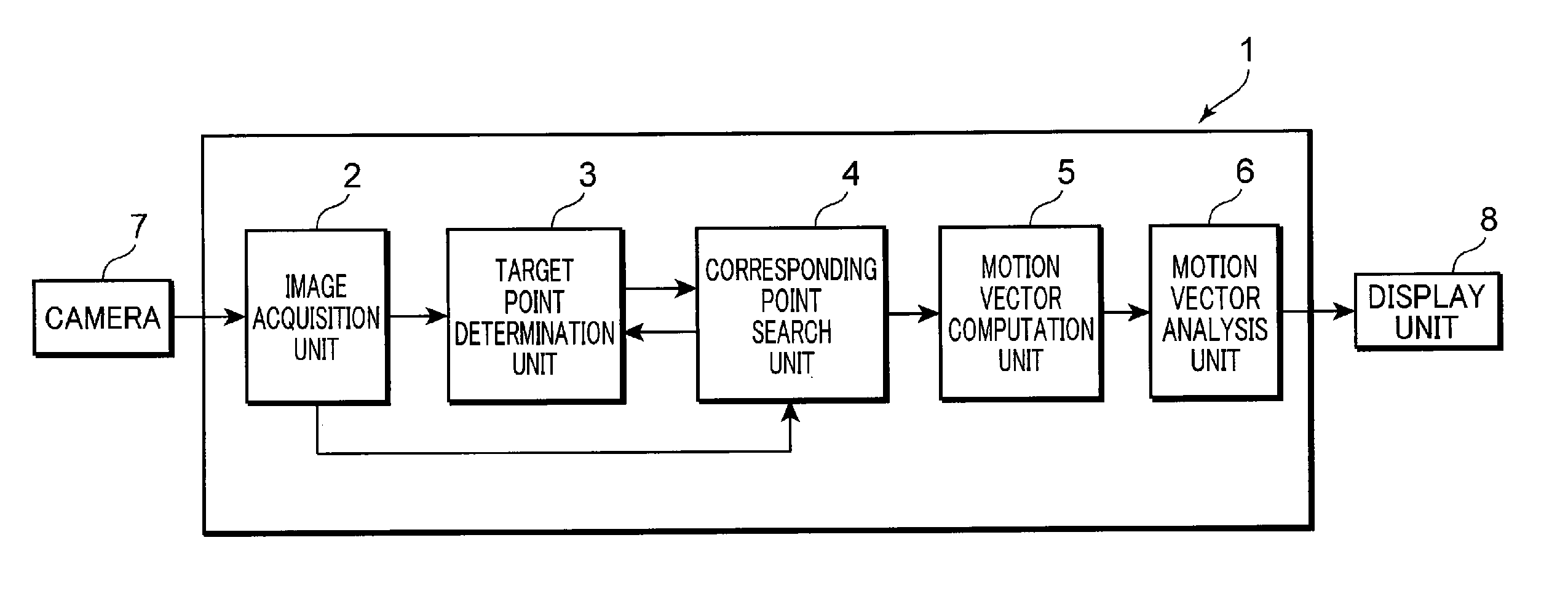
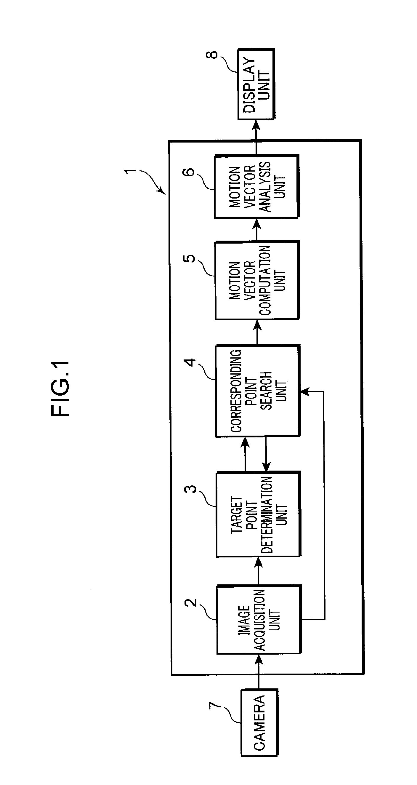
[0032]First, a configuration of a motion vector generation apparatus according to an embodiment of the present invention is described. FIG. 1 is a block diagram showing a configuration of a motion vector generation apparatus according to this embodiment. As shown in FIG. 1, a motion vector generation apparatus 1 comprises an image acquisition unit 2, a target point determination unit 3, a corresponding point search unit 4, a motion vector calculation unit 5, and a motion vector analysis unit 6. The motion vector generation apparatus 1 is made up of, for example, electronic components and integrated circuit components, a CPU (Central Processing Unit), and a storage unit. The motion vector generation apparatus 1 is connected to a camera 7 and a display uni...


PUM


Abstract

In a motion vector generation apparatus 1 according to the present invention, when motion vectors are sequentially generated for a plurality of images, a target point is determined at a sub-pixel level in any of the plurality of images, a corresponding point corresponding to the target point is searched at the sub-pixel level in another image different from this image, and a motion vector is calculated on the basis of the target point and the corresponding point. Then, the corresponding point is defined as a new target point, and the aforementioned process is repeated to sequentially generate the motion vectors. Thus, the motion vector generation apparatus 1 of the present invention can compute consecutive motion vectors by performing correspondence search at the sub-pixel level in the plurality of images.

Description

TECHNICAL FIELD[0001]The present invention relates to a motion vector generation apparatus and a motion vector generation method for generating motion vectors by means of correspondence search between time-series images.BACKGROUND ART[0002]Various systems have been investigated for further safety improvements in recent automotive industry. In particular, image sensors equipped with a camera are employed. The image sensors are used for identification of an object and motion analysis of the object through the image processing of the captured images.[0003]Motion analysis may be performed using, for example, a correlation technique. The correlation technique is based on finding, in the two images corresponding to each other, a point (corresponding point) in one of the images that corresponds to a target point in another image. More specifically, according to this correlation technique, a template is selected in the preceding image, i.e., an image of interest out of, for example, two tim...

Claims


Application Information

Patent Timeline
Patent Type & Authority Applications(United States)
IPC IPC(8): H04N7/32B60R1/00G06T7/20
CPCG06T7/204G06T7/2086H04N5/145H04N19/597H04N19/523G06T2207/10021G06T7/248G06T7/285
Inventor SUMITOMO, HIRONORI
Owner KONICA MINOLTA INC
Why Eureka
Try Eureka