Acoustical Fluid Control Mechanism

a fluid control and acoustic technology, applied in the field of acoustic, can solve the problems of insufficient external connections and control equipment required to operate a reasonably complex integrated microfluidic system, difficulty in controlling fluid flow, and difficulty in controlling liquid reagents and samples, so as to eliminate directional flow and maximize the oscillation flow of working fluid

Active Publication Date: 2011-11-17
RGT UNIV OF MICHIGAN
View PDF9 Cites 10 Cited by
  • Summary
  • Abstract
  • Description
  • Claims
  • Application Information

AI Technical Summary

Benefits of technology

The patent text describes a new fluid control mechanism that can be used in integrated microfluidic systems. This mechanism uses acoustics to control the frequency of a working fluid in response to an acoustic signal. The mechanism includes a resonance chamber that produces oscillatory flow of the fluid. This technology overcomes the limitations of existing control methods, which require external liquid or air pressure and have difficulty controlling fluid flow. The acoustical fluid control mechanism is small and can be used in microfluidic systems for various applications.

Problems solved by technology

Control and transport of the liquid reagents and samples are difficulties that are often encountered with the integrated microfluidic systems.
Use of the external liquid or air pressure often requires the use of extensive external control equipment, and difficulties with control of fluid flow often arise due to the use of multiple pumps dedicated to each fluidic unit.
With this approach, multiplexed pressure control is feasible, but the number of external connections and control equipment required to operate a reasonably complex integrated microfluidic system is prohibitively large in size, and such an approach also requires high power actuation schemes.
The dependence on external liquid or air pressure is becoming increasingly problematic with the push towards integrated microfluidic systems, which can include thousands of independent pressure regulators.
Additionally, the lack of low power actuation schemes has, in part, hindered the use of the systems for various applications.
However, due to an intolerance to back pressure, microfluidic applications using acoustic streaming have thus far been limited primarily to driving closed-loop fluid circuits.
One limitation to the use of SAWs, in addition to potential limitations introduced from use of an open platform (such as reagent and sample storage, evaporation losses, contamination), is fabricating the numbers of electrodes necessary for precise droplet placement.
As such, acoustic compressors tend to be physically large for a given pumping capacity, when compared to other types of compressors, which is especially detrimental for microfluidic systems.

Method used


Image

  • Acoustical Fluid Control Mechanism
  • Acoustical Fluid Control Mechanism
  • Acoustical Fluid Control Mechanism

Examples


Embodiment Construction

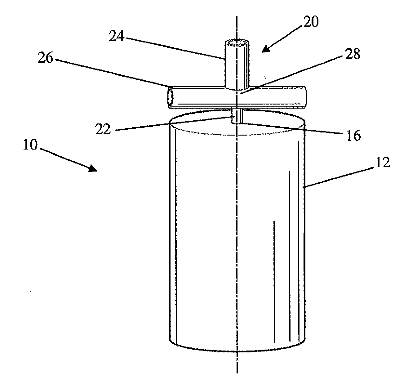
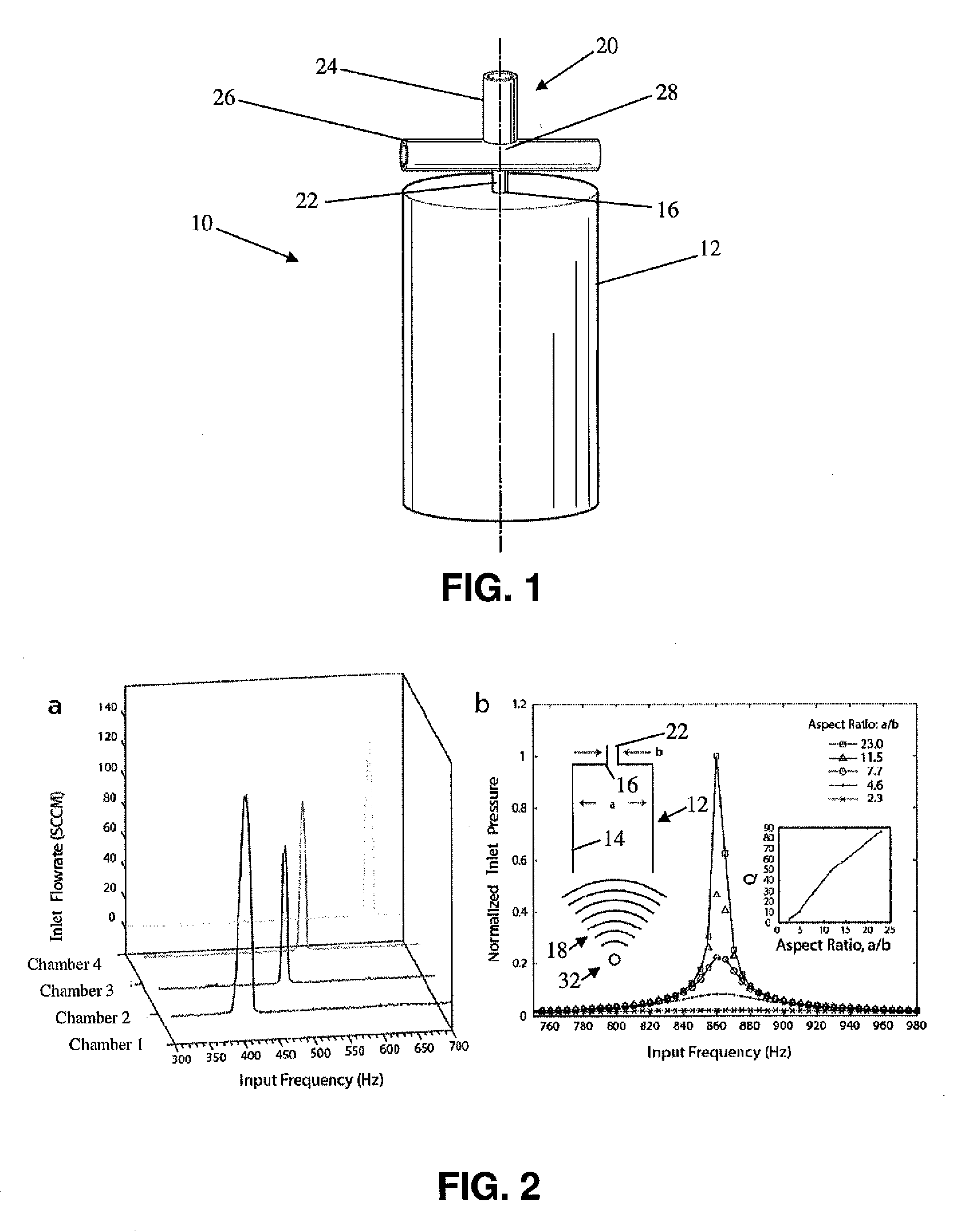
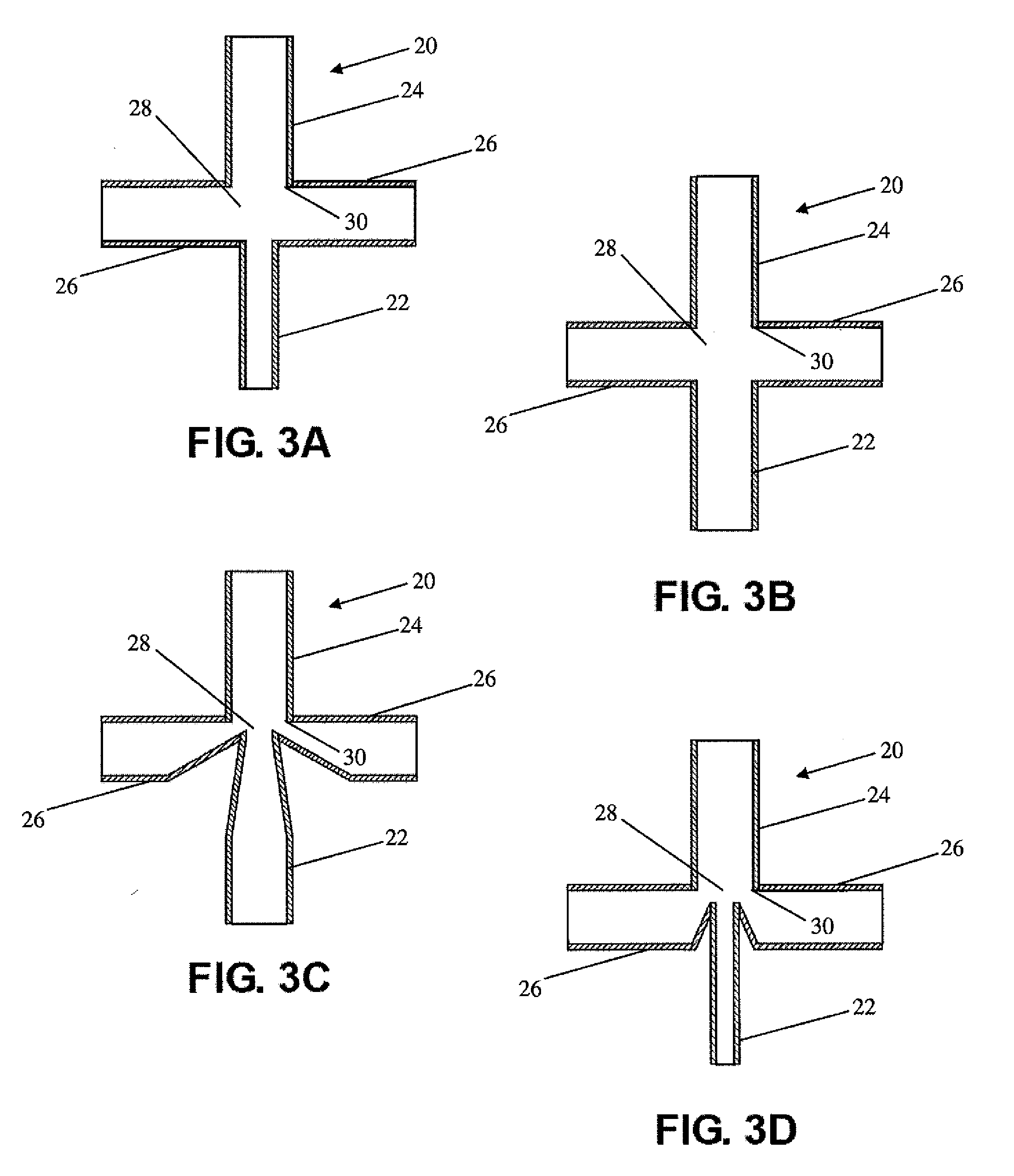
[0026]Referring to the Figures, wherein like numerals indicate like or corresponding parts, an acoustical fluid control mechanism 10 is generally shown at 10 in FIG. 1. The acoustical fluid control mechanism 10 of the instant invention includes a resonance chamber 12 and, more typically, includes a bank of resonance chambers 12 as shown in FIG. 6. Each resonance chamber 12 defines a cavity 14. The resonance chamber 12 (or bank of resonance chambers 12) is designed using principles of resonance and has a geometry that corresponds to a particular resonance frequency. For example, the resonance chamber(s) 12 can be designed using principles of standing wave resonance or Helmholtz resonance, both of which are known in the art. As also known in the art, “resonance frequency” refers to a frequency at which a system tends to oscillate at a larger amplitude than at other frequencies, and typically represents the frequency or frequencies at which maximum oscillation of the system occurs due ...


PUM


Abstract

An acoustical fluid control mechanism and a method of controlling fluid flow of a working fluid with the acoustical fluid control mechanism are provided. The mechanism comprises a resonance chamber that defines a cavity. The resonance chamber has a port. The cavity is sealed from the ambient but for the port for enabling oscillatory flow of a working fluid into and out of the cavity upon exposure of the resonance chamber to an acoustic signal containing a tone at a frequency that is substantially similar to a particular resonance frequency of the resonance chamber. The mechanism further includes a rectifier for introducing directional bias to the oscillatory flow of the working fluid through the port. The rectifier has an inlet connected to the port and an outlet for transmitting the directional flow of the working fluid away from the cavity. The outlet is in fluid communication with the port of the resonance chamber at least during transmission of the directional flow of the working fluid therethrough.

Description

CROSS-REFERENCE TO RELATED APPLICATIONS[0001]This application claims priority to and all the advantages of U.S. Provisional Patent Application No. 61 / 199,290, filed on Nov. 14, 2008.GOVERNMENT LICENSING RIGHTS[0002]This invention was made with government support under grant number AI049541 awarded by the National Institute of Health. The government has certain rights in the invention.BACKGROUND OF THE INVENTION[0003]1. Field of the Invention[0004]The instant invention generally relates to a fluid control mechanism by which the frequency constituents within an acoustic signal are converted to a useful working output. More specifically, the instant invention relates to a fluid control mechanism including a resonance chamber that produces oscillatory flow of a working fluid in response to exposure to an acoustic signal.[0005]2. Description of the Related Art[0006]A wide variety of actuating technologies have been developed for use in miniaturized systems for the life sciences including...

Claims


Application Information

Patent Timeline
Patent Type & Authority Applications(United States)
IPC IPC(8): F15D1/00
CPCF04B17/00F04F7/00F04B19/006Y10T137/2224Y10T137/0391Y10T137/2196
Inventor BURNS, MARK A.LANGELIER, SEAN M.CHANG, DUSTIN S.
Owner RGT UNIV OF MICHIGAN
Why Eureka
Try Eureka