Slide switch

Inactive Publication Date: 2011-11-17
DELTA KOGYO CO LTD
View PDF1 Cites 0 Cited by
  • Summary
  • Abstract
  • Description
  • Claims
  • Application Information

AI Technical Summary

Benefits of technology

[0011]In view of the above problems, it is therefore an object of the present invention to provide a slide switch capable of suppressing the occurrence of a problem with switch functions even if it is used in both a key interlock system where a large current is applied thereto and a key interlock system where a small current is applied thereto.

Problems solved by technology

If a small current is applied to the large-current slide switch 2(A), a contact failure between switch contacts is likely to occur due to an oxide film or the like.
If a large current is applied to the small-current slide switch 2(B), switch contacts are likely to degrade due to arc discharge.
However, in cases where the large-current slide switch 2(A) and the small-current slide switch 2(B) are selectively used depending on the types of key interlock systems, an operation of installing the slide switch will become complicated.
Moreover, there is a risk that an operator wrongly selects the type of slide switch to be installed.
Further, it is necessary to produce and manage the two types of slide switches, which leads to an increase in cost.

Method used


Image

  • Slide switch
  • Slide switch
  • Slide switch

Examples


Embodiment Construction

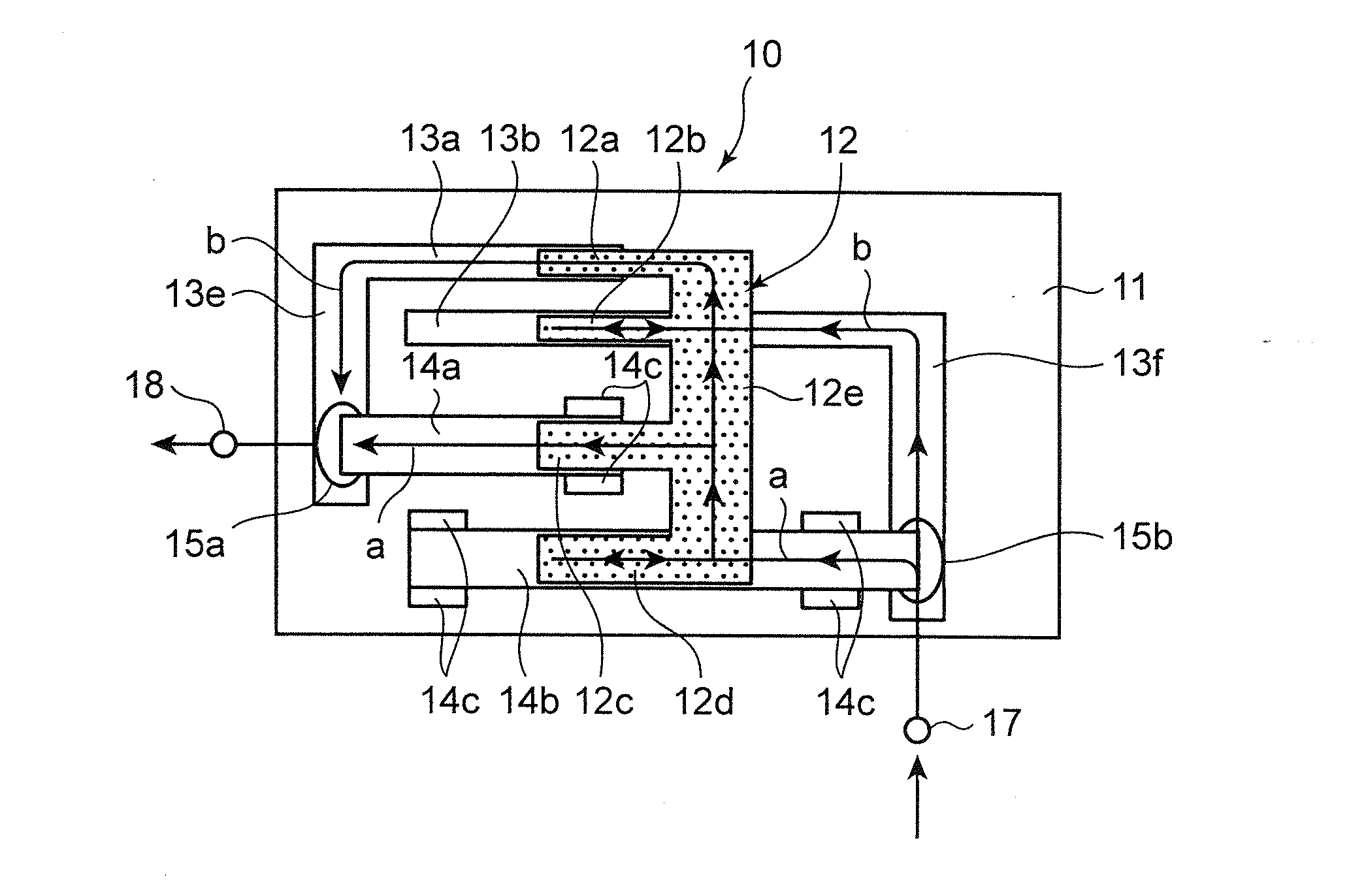
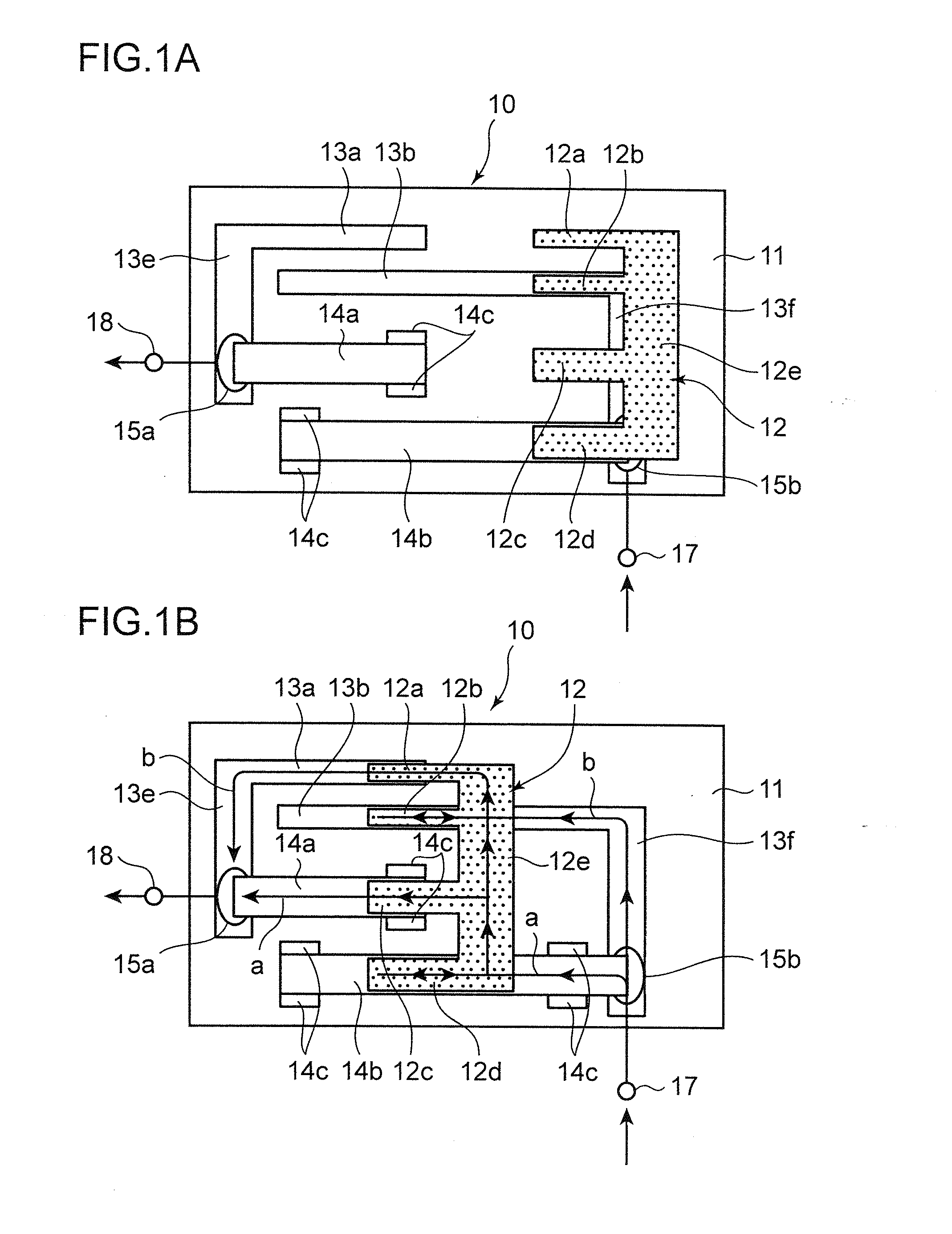
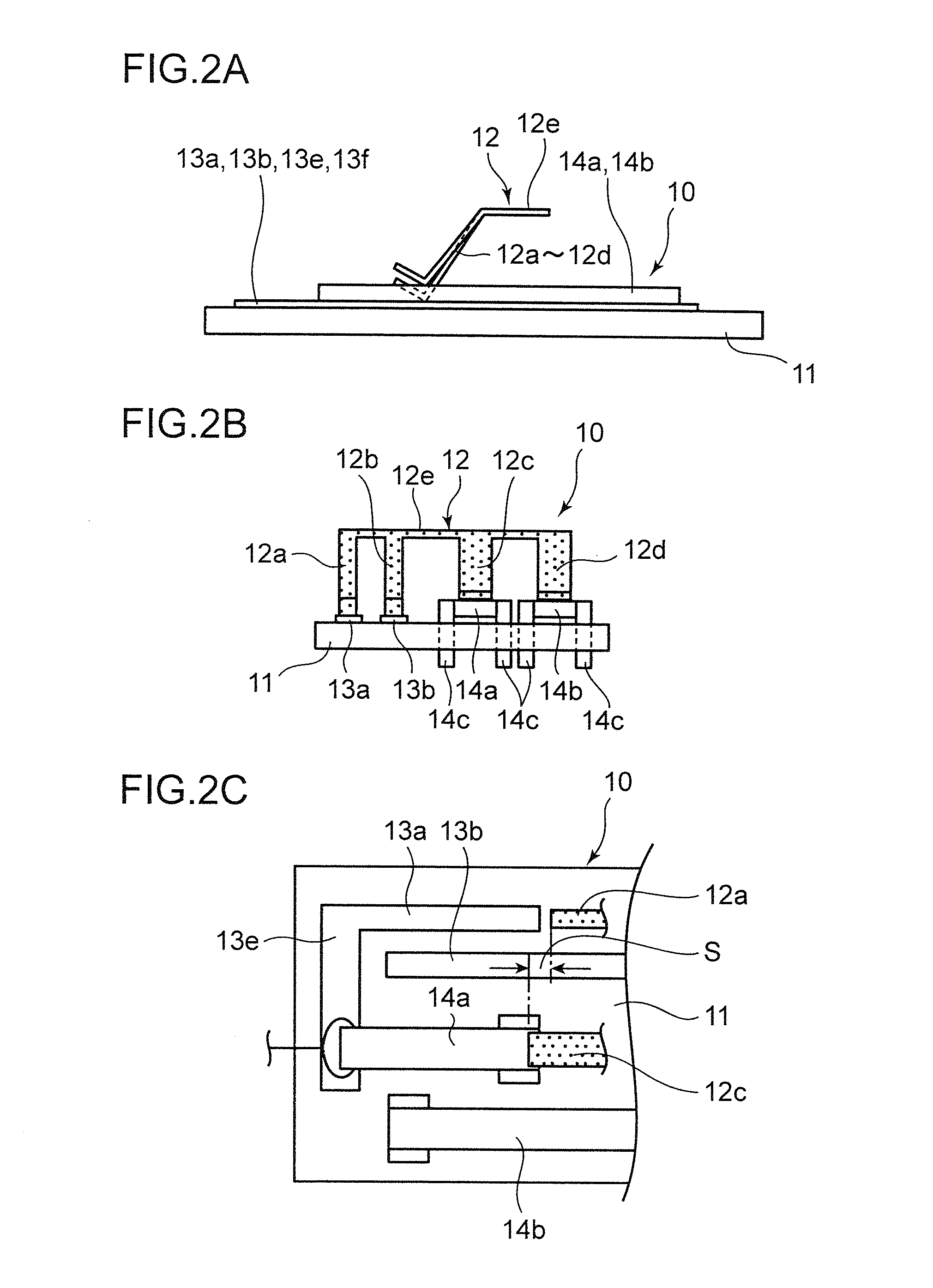
[0018]With reference to the drawings, a slide switch 10 according to one embodiment of the present invention will now be specifically described. As illustrated in FIGS. 1A, 1B, 2A and 2B, the slide switch 10 comprises a rectangular-shaped board 11, a fixed contact disposed on a surface of the board 11, and a movable contact member 12 slidingly movable along the board 11 and the fixed contact.

[0019]The fixed contact includes a pair of small-current fixed contacts (a first small-current fixed contact 13a and a second small-current fixed contact 13b), and a pair of large-current fixed contacts (a first large-current fixed contact 14a and a second large-current fixed contact 14b). In FIGS. 1A to 2B, dots are assigned to the movable contact member 12 to facilitate visualizing a relationship with each of the fixed contacts 13a, 13b, 14a, 14b.

[0020]Each of the small-current fixed contacts 13a, 13b is formed by printing a wiring pattern on a surface of the board 11. The small-current fixed...


PUM


Abstract

A slide switch has a first small-current fixed contact, a second small-current fixed contact, a first large-current fixed contact and a second large-current fixed contact all disposed on a board. A movable contact member is movable along the board and includes a first small-current movable contact, a second small-current movable contact, a first large-current movable contact and a second large-current movable contact, all of which are integrally formed together. The first small-current movable contact is adapted, according to the movement of the movable contact member, to be brought into contact with the first small-current fixed contact. The first large-current movable contact is adapted, according to the movement of the movable contact member, to contact the first large-current fixed contact. The second small-current movable contact is continually in contact with the second small-current fixed contact. The second large-current movable contact is continually in contact with the second large-current fixed contact.

Description

BACKGROUND OF THE INVENTION[0001]1. Field of the Invention[0002]The present invention relates to a slide switch.[0003]2. Description of the Related Art[0004]Heretofore, there has been known a key interlock system which is designed, when a shift lever of a shifter mechanism of an automatic transmission vehicle is in a position other than a P (Parking) range position, to make it unable to pull out an engine key from a key cylinder even if the key is turned to a LOCK position (or OFF position) (see JP 8-233078A).[0005]As illustrated in FIG. 3A, in the conventional key interlock system, a slide switch 2(A) is adapted to be set to an ON state in a manner interlocked with an operation of moving a shift lever 1 to a P range position, to thereby cause a key pull-out preventing solenoid 3 to be set to an ON state. This makes it possible to pull out an engine key 4 from a key cylinder 5. In this type of key interlock system, a large current (several hundred mA, e.g., 400 to 700 mA) is applied...

Claims


Application Information

Patent Timeline
IPC IPC(8): H01H15/00
CPCF16H59/105H01H1/40H01H2011/0093H01H15/04H01H15/06H01H1/403
Inventor UJIMOTO, TAKUSHINAKAHIRA, HIROSHIUETA, MIZUHO
Owner DELTA KOGYO CO LTD
Why Eureka
Try Eureka