Gas sensor

Active Publication Date: 2019-06-13
NISSHA PRINTING COMPANY
View PDF0 Cites 0 Cited by
  • Summary
  • Abstract
  • Description
  • Claims
  • Application Information

AI Technical Summary

Benefits of technology

The gas sensor in this patent is designed to be smaller and more compact, while also being able to detect gas accurately even in very low temperatures. This means that it can be made more easily and with less power than existing gas sensors.

Problems solved by technology

In a case where the frost reaches the resistor, the frost will inhibit the diffusion of hydrogen and worsen the hydrogen detection accuracy.

Method used


Image

  • Gas sensor
  • Gas sensor
  • Gas sensor

Examples


first embodiment

[0036]A gas sensor configured to detect hydrogen that produces water when combusted will be described hereinafter as an example of a gas sensor according to a first embodiment of the present invention. However, the detection target of the gas sensor according to the present invention is not limited to hydrogen. Methane, propane, and butane can also be given as examples of detection targets that produce water when combusted.

[0037]Before describing the gas sensor, a gas detection device using the gas sensor will be described briefly.

(1) Gas Detection Device Using Gas Sensor

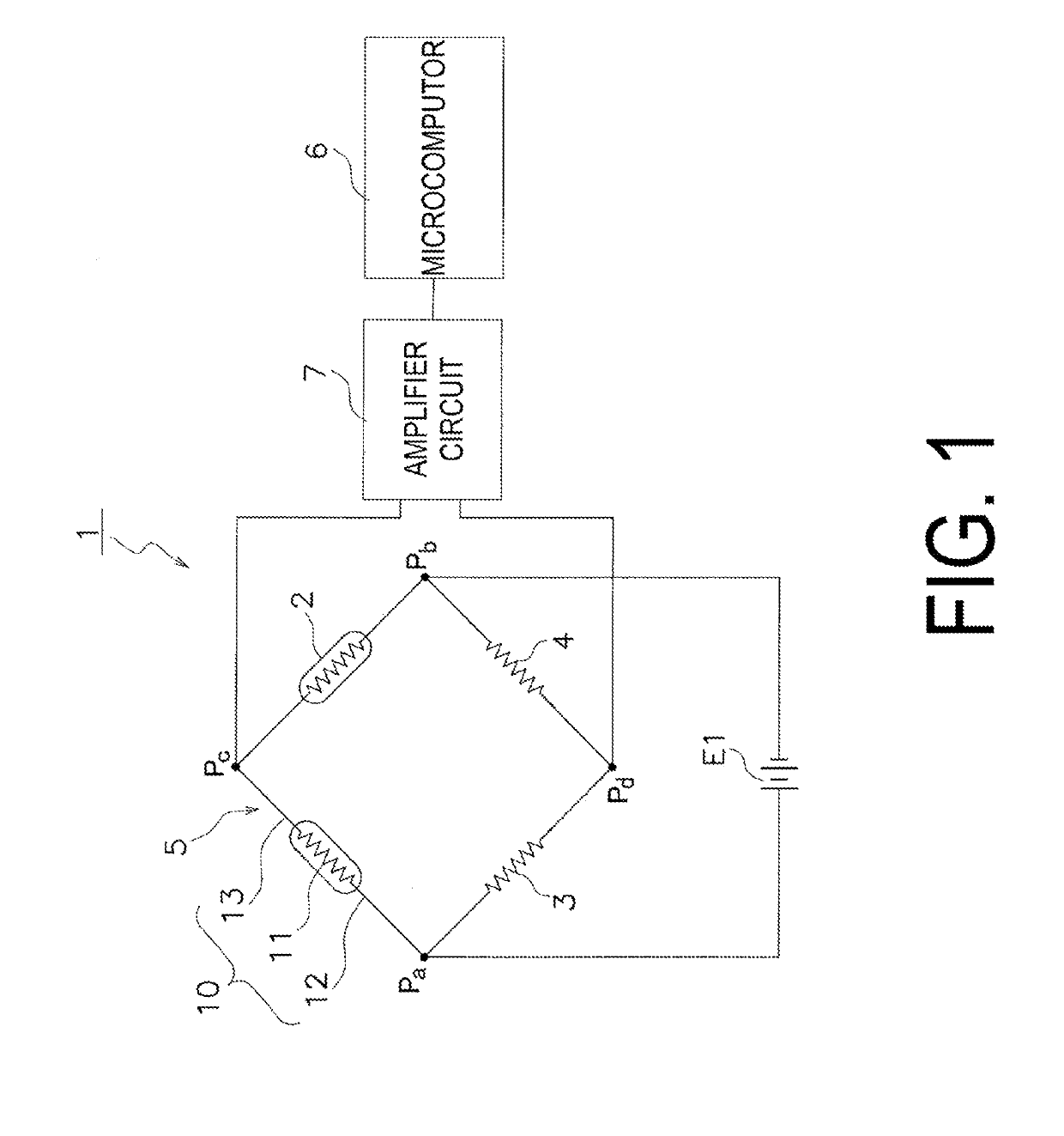
[0038]FIG. 1 schematically illustrates an example of a measurement circuit of a gas detection device 1 that uses a gas sensor 10. The measurement circuit of the gas detection device 1 includes a bridge circuit 5 constituted by the gas sensor 10, a compensation element 2, a first fixed resistor 3, and a second fixed resistor 4. A first electrode terminal 12, which is one terminal of the gas sensor 10, is connected to...

second embodiment

[0064]Although the first embodiment of the present invention has been described above, the present invention is not limited to the foregoing embodiment, and many variations are possible without departing from the essential spirit of the invention. In particular, multiple embodiments and variations described in this specification can be combined optionally, as needed.

[0065]The foregoing first embodiment describes a case where mounted components that produce heat by themselves are not taken into consideration. However, as illustrated in FIG. 13, a mounted component 30 that produces heat by itself may be disposed nearby the gas sensor 10 and combined with the gas sensor 10. In this case, it is preferable that the mounted component that produces heat by itself be a mounted component that operates along with the operation of an electric circuit into which the gas sensor 10 is incorporated. A chip resistor of the electric circuit into which the gas sensor 10 is incorporated can be given a...

third embodiment

[0066]The foregoing second embodiment describes a case where the bottom surface 90a of the printed circuit board 90 directly above the resistor 11 is heated using the mounted component 30, which produces heat by itself. However, the mounted component 30 may instead be a dedicated heater. It is sufficient that the dedicated heater prevent frost from being formed in particular. As such, the heater need not heat to the boiling point of water or above. For example, the heater is configured to turn off at a switching temperature of from 1° C. to 50° C., and more preferably, from 5° C. to 10° C. For example, the heater can be configured to turn off when the temperature reaches 5° C. by using a temperature sensor and a switching element. In a case where the gas sensor 10 is installed in an automobile, the power for driving the gas sensor 10 and the heater is taken from the battery of the automobile, and it is therefore necessary to drive the gas sensor 10 and the heater with as little powe...


PUM


Abstract

Object:To provide a gas sensor having a small size and that can suppress gas detection problems caused by frost using only a small amount of power.Solution: A first electrode terminal (12) includes at least one first connection part (121) connected to a first wire and a first arm part (123) extending from the first connection part (121) to one end (11a) of a resistor (11). A second electrode terminal (13) includes at least one second connection part (131) connected to a second wire and a second arm part (133) extending from the second connection part (131) to the other end (11b) of the resistor (11). The first electrode terminal (12) and the second electrode terminal (13) are fixed to each other and form a water vapor diffusion cavity (S2) extending from the resistor (11) to a wiring member or the vicinity of the wiring member, with at least part of the first arm part (123) and at least part of the second arm part (133) coated with insulation.

Description

CROSS-REFERENCE TO RELATED APPLICATION[0001]The present application is based on PCT filing PCT / JP2017 / 029947, filed Aug. 22, 2017, which claims priority to JP 2016-164426, filed Aug. 25, 2016, the entire contents of which are incorporated herein by referenceTECHNICAL FIELD[0002]The present invention relates to a gas sensor that detects a gas which produces water when being combusted using a catalyst.BACKGROUND ART[0003]In recent years, hydrogen fuel cells are being put into practical use, giving rise to demand for gas sensors that detect hydrogen. Hydrogen is detected by a catalytic combustion gas sensor. This sensor uses a resistor holding a catalyst containing platinum, palladium, or rhodium, for example, which causes hydrogen to combust, on a metal wire formed from a metal such as platinum or palladium or an alloy thereof. The catalytic combustion gas sensor detects hydrogen using changes in the resistance value of the resistor, which occur when the hydrogen burns and the tempera...

Claims


Application Information

Patent Timeline
IPC IPC(8): G01N27/16G01N33/00
CPCG01N27/16G01N33/005G01N33/006
Inventor MATSUMOTO, TAKASHIKIRA, MITSUHARUYAMAMOTO, HIROKIKUWAHARA, YURI
Owner NISSHA PRINTING COMPANY
Why Eureka
Try Eureka