Terminal connecting structure and electronic component

Active Publication Date: 2022-03-17
KOA CORP
View PDF0 Cites 0 Cited by
  • Summary
  • Abstract
  • Description
  • Claims
  • Application Information

AI Technical Summary

Benefits of technology

The present invention aims to address the issue of excessive usage of connecting material used to connect terminals and electrodes. By ensuring a consistent and optimal amount of material between the two components, the invention aims to prevent problems associated with overuse or uneven usage of the connecting material. This results in a more stable and reliable connection between the terminal and electrode.

Problems solved by technology

As a result, in order to protect fragile electronic circuits from unexpected noise or pulse with large energy, requirements for the electronic components to be mounted on the equipment have become quite severe.
However, even if the bulk size of a conventional surface mounted varistor is increased for the high voltage / large current pulse, when the varistor is short circuited by a pulse caused by lightning surge, etc., the component itself is heated to about 1000° C. In a terminal connecting structure in such electronic components, if a used amount (supplied amount, filled amount) of a connecting material formed of a solder for electrically connecting the electrode and the terminal is small, a suitable bonding strength cannot be ensured.
In addition, if an excessive amount of the connecting material is used, the thickness dimension of the solder becomes excessive, and there is a risk in that the terminal or the element is exposed from an outer package.
In addition, there is a problem that it leads to the excessive increase in a product size and an increase in a cost.

Method used


Image

  • Terminal connecting structure and electronic component
  • Terminal connecting structure and electronic component
  • Terminal connecting structure and electronic component

Examples


first embodiment

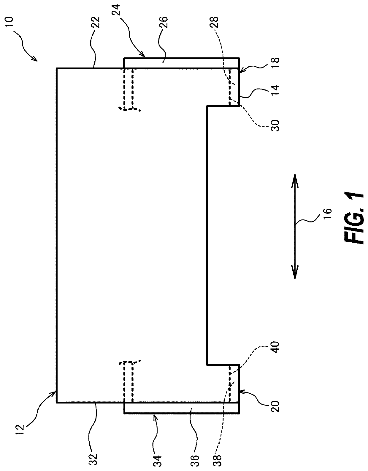
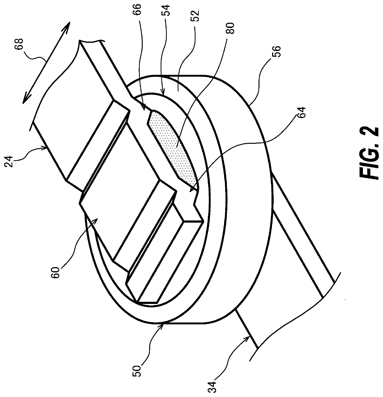
[0020]An electronic component provided with a terminal connecting structure according to a first embodiment will be described with reference to FIGS. 1 to 3. FIG. 1 is a side view showing an electronic component 10 according to the first embodiment.

[0021]The electronic component 10 includes a varistor, a resistor, a capacitor, a thermistor, a semiconductor, or various types of sensor elements, or the like to which these components are applied. In this embodiment, a case in which the electronic component 10 is the varistor will be described as an example. The varistor is the electronic component 10 having a pair of metal terminals in which a ceramic element is sandwiched between the metal terminals, and has a durability capable of tolerating usage environments in which a high voltage and large current, such as lightning surge, etc., for example, are applied.

[0022]The electronic component 10 is provided with a component main body 12 having a rectangular shape, for example. The compone...

second embodiment

[0068]FIG. 4 is a side view showing the inside of an electronic component 100 according to the second embodiment and shows the figure corresponding to FIG. 3 for the first embodiment.

[0069]The second embodiment will be described by using FIG. 4. Components that are the same as or similar to those in the first embodiment will be assigned the same reference numerals, and a description thereof shall be omitted. Description will be given of components that are different from those in the first embodiment.

[0070]In the electronic component 100 provided with the terminal connecting structure of the second embodiment, each of the electrodes 54, 58 has a smaller external dimension compared with the first electrode 54 and the second electrode 58 of the first embodiment. Therefore, the projected portions 64, 66, 70, 72 formed on the respective terminals 24, 34 each comes into contact with the element 50 at an outer circumferential portion of each of the corresponding electrodes 54, 58.

[0071]In...

third embodiment

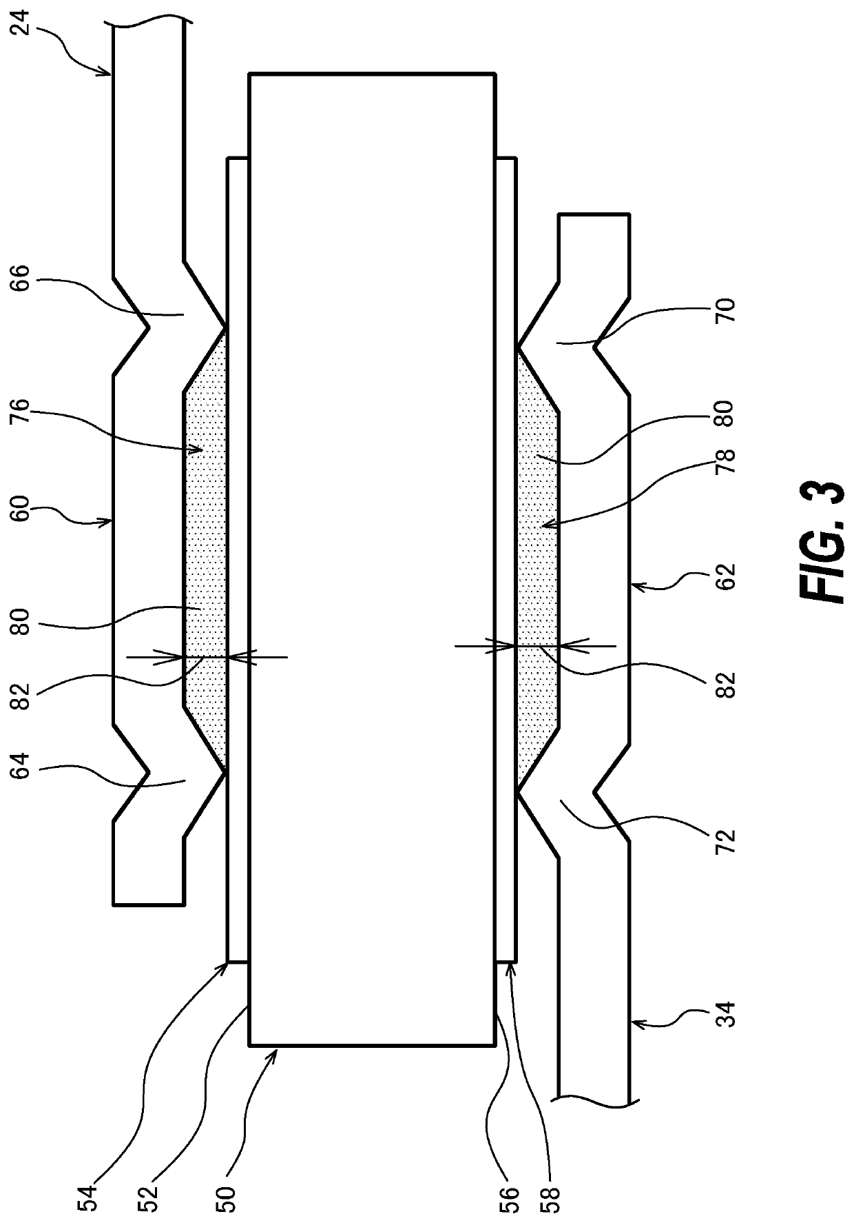
[0077]FIG. 5 is a perspective view showing the inside of an electronic component 200 according to a third embodiment and shows the figure corresponding to FIG. 2 for the first embodiment. FIG. 6 is a side view showing the inside of the electronic component 200 according to the third embodiment and shows the figure corresponding to FIG. 3 for the first embodiment.

[0078]The third embodiment will be described by using these FIGS. 5 and 6. Components that are the same as or similar to those in the first embodiment will be assigned the same reference numerals, and a description thereof shall be omitted. Description will be given of components that are different from those in the first embodiment.

[0079]In the electronic component 200 provided with the terminal connecting structure of the third embodiment, the shapes of the projected portions 64, 66, 70, 72 formed on the respective terminals 24, 34 are different compared with the first terminal 24 and the second terminal 34 in the first em...


PUM


Abstract

A terminal connecting structure is provided with each of the electrodes provided on the element forming the electronic component; and the terminals respectively having the connecting portions arranged along the electrodes respectively. In addition, the terminal connecting structure is provided with clearance forming portions configured to respectively form the respective clearances between the electrodes and the connecting portions respectively; and the connecting materials respectively provided in the clearances, the connecting material being configured to electrically connect the connecting portions and the electrodes respectively.

Description

CROSS-REFERENCE TO RELATED APPLICATIONS[0001]This application claims priority of Japanese Patent Application No. JP 2020-156249 filed on Sep. 17, 2020, the contents of which are incorporated herein.TECHNICAL FIELD[0002]The present disclosure relates to a terminal connecting structure and an electronic component.BACKGROUND ART[0003]In recent years, there have been drastic changes in usage environments for electronic components used for automobiles, household electrical appliances, industrial equipment, etc. There has been revisions of the standards, which had not been requested so far, for the electronic components of these kinds. In addition, the applications of the components have been increasingly diversified for the electronic components of these kinds. As a result, in order to protect fragile electronic circuits from unexpected noise or pulse with large energy, requirements for the electronic components to be mounted on the equipment have become quite severe. A varistor that is ...

Claims


Application Information

Patent Timeline
IPC IPC(8): H01C7/12
CPCH01C7/12H01C7/112H01C7/10H01C1/14H01C7/102H01C1/148
Inventor TONOUCHI, ISAO
Owner KOA CORP
Why Eureka
Try Eureka