Light fixture with flameless candle

a technology of flameless candles and light fixtures, applied in the field of light fixtures, can solve problems such as not being accomplished otherwis

Inactive Publication Date: 2011-11-17
LUCAS SCOTT +6
View PDF8 Cites 22 Cited by
  • Summary
  • Abstract
  • Description
  • Claims
  • Application Information

AI Technical Summary

Benefits of technology

[0011]Various objects, features, aspects and advantages of the inventive subject matter will become more apparent from the following ...

Problems solved by technology

Such difference in brightness is critical to produce the conflicting amounts of...

Method used


Image

  • Light fixture with flameless candle
  • Light fixture with flameless candle
  • Light fixture with flameless candle

Examples


Embodiment Construction

[0015]The following discussion provides many example embodiments of the inventive subject matter. Although each embodiment represents a single combination of inventive elements, the inventive subject matter is considered to include all possible combinations of the disclosed elements. Thus if one embodiment comprises elements A, B, and C, and a second embodiment comprises elements B and D, then the inventive subject matter is also considered to include other remaining combinations of A, B, C, or D, even if not explicitly disclosed.

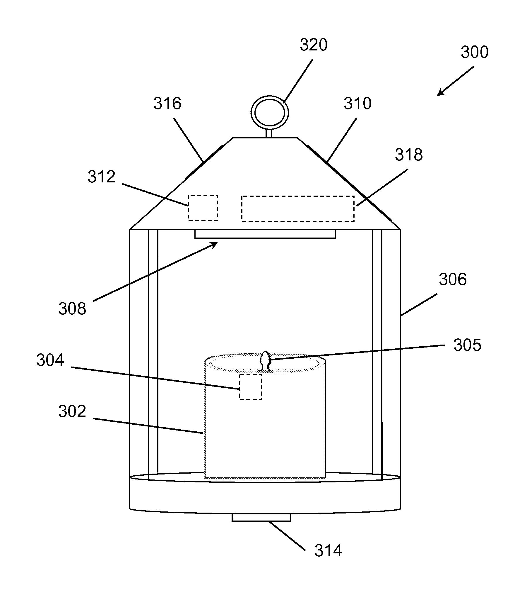
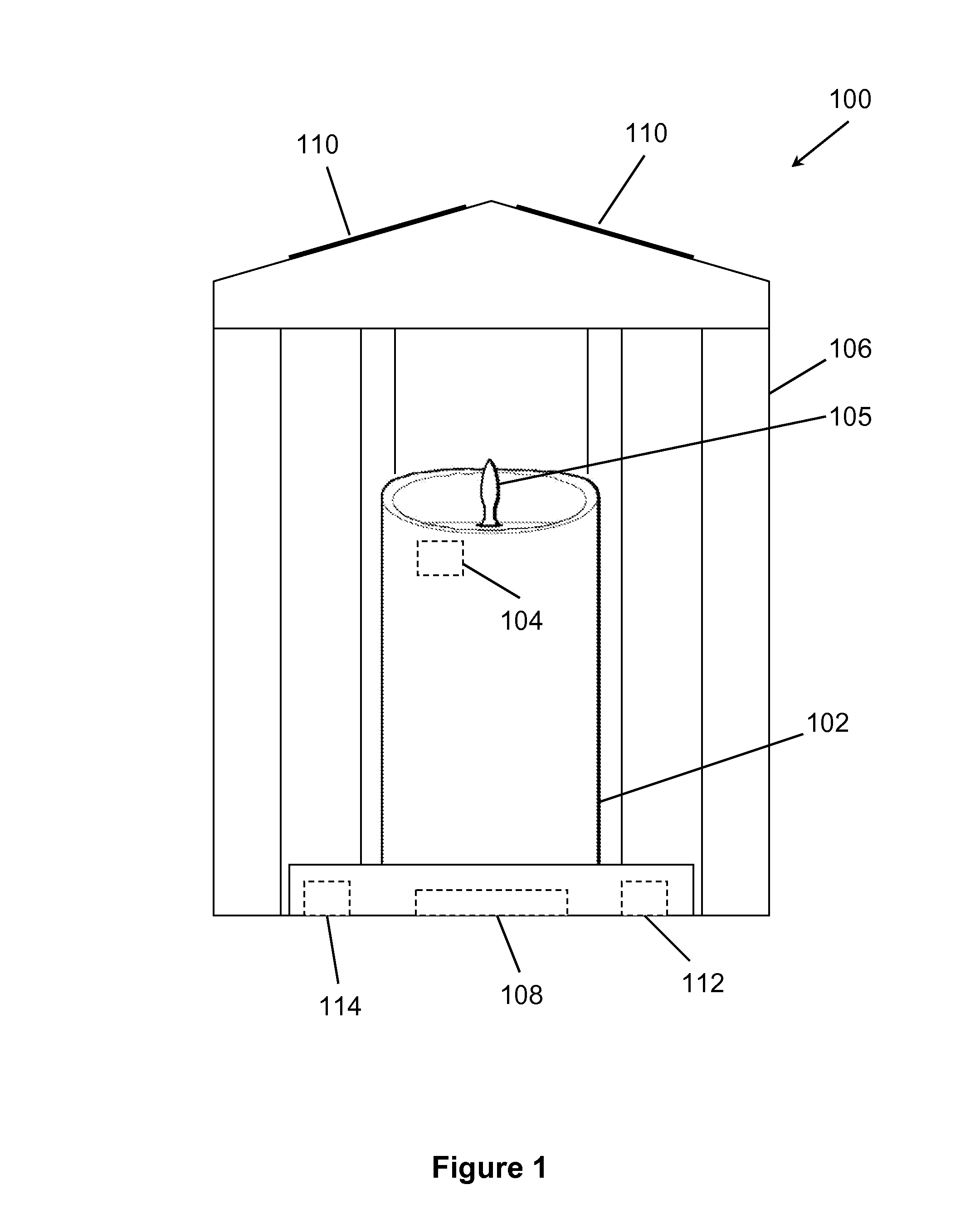
[0016]In FIG. 1, a light fixture 100 is shown that includes a flameless candle 102 having a light source 104. Exemplary flameless candles are discussed in U.S. Pat. Nos. 7,159,994 and 7,261,455, and U.S. patent publ. no. 2011 / 0019422 to Schnuckle et al. (publ. January 2011), although any commercially suitable flameless candle could be used that produce a flickering flame effect. Preferred flameless candles include one or more LEDs with a teardrop or flame-s...


PUM


Abstract

Light fixtures are disclosed having a first light source. The light fixtures can include a second light source, and a flameless candle that includes the first light source. A sensor can also be included that is configured to detect at least one of movement and light, and produces a sensor signal.

Description

[0001]This application claims the benefit of priority to U.S. provisional application having Ser. No. 61 / 324,266 filed on Apr. 14, 2010. This and all other extrinsic materials discussed herein are incorporated by reference in their entirety. Where a definition or use of a term in an incorporated reference is inconsistent or contrary to the definition of that term provided herein, the definition of that term provided herein applies and the definition of that term in the reference does not apply.FIELD OF THE INVENTION[0002]The field of the invention is light fixtures.BACKGROUND[0003]Various systems and methods are known in the art to create a flickering flame effect. See, for example, U.S. Pat. No. 7,159,994 to Schnuckle et al. and U.S. Pat. No. 7,261,455 to Schnuckle et al. Although the Schnuckle devices can be useful for novelty purposes, they are impractical where greater amounts of light are needed, especially in outdoor locations.[0004]U.S. Pat. No. 7,377,667 to Richmond discusse...

Claims


Application Information

Patent Timeline
IPC IPC(8): H05B37/02F21V21/00
CPCF21S9/03F21V23/0464F21V23/0471F21Y2101/02F21W2111/023H05B37/0218H05B37/0227Y02B20/46F21Y2113/02F21Y2113/20F21Y2115/10H05B47/105H05B47/11H05B47/115Y02B20/40
Inventor LUCAS, SCOTTTHOMPSON, JEFFSMITH, PETERGAST, BOBYOUNG, ALLENGRAY, CAROLINEMCKINNON, ALEX
Owner LUCAS SCOTT
Why Eureka
Try Eureka