System and apparatus for locomotive radio communications

a technology for radio communications and equipment, applied in the direction of antenna details, antenna adaptation in movable bodies, antennas, etc., can solve the problems of requiring further maintenance time, affecting the service life of the locomotive, so as to reduce the number of holes in the roof, reduce the maintenance time of the locomotive, and reduce the effect of water intrusion

Active Publication Date: 2011-11-17
GE GLOBAL SOURCING LLC
View PDF7 Cites 56 Cited by
  • Summary
  • Abstract
  • Description
  • Claims
  • Application Information

AI Technical Summary

Benefits of technology

[0003]An apparatus for locomotive radio communications is provided for removably electrically connecting antennas to a roof of the locomotive. In one embodiment, the radio communication system comprises a removable antenna platform and an antenna interface bulkhead connected to the roof of the locomotive. The antenna platform includes a first blind mate connector connected to an antenna mount. The antenna mount is connected to a ground plane. The antenna interface bulkhead includes a second blind mate connector configured to mate with the blind mate connector of the antenna platform when the antenna platform is attached to the antenna interface bulkhead. The antenna interface bulkhead and antenna platform are configured to attach to one another in one orientation only. Thus, one or more antennas may be quickly attached to or removed from the roof of the locomotive, reducing maintenance time for the locomotive when an antenna upgrade may be desired. In addition, water intrusion may be reduced by reducing the number of holes in the roof of the locomotive and by forming a water resistant seal at the antenna interface bulkhead.

Problems solved by technology

This solution may be time consuming and costly due to labor costs and non-productive maintenance time of the locomotive.
In addition, the mounting area of the antenna may be subject to water intrusion, which may result in damaged equipment and / or require further maintenance time.

Method used


Image

  • System and apparatus for locomotive radio communications
  • System and apparatus for locomotive radio communications
  • System and apparatus for locomotive radio communications

Examples


Embodiment Construction

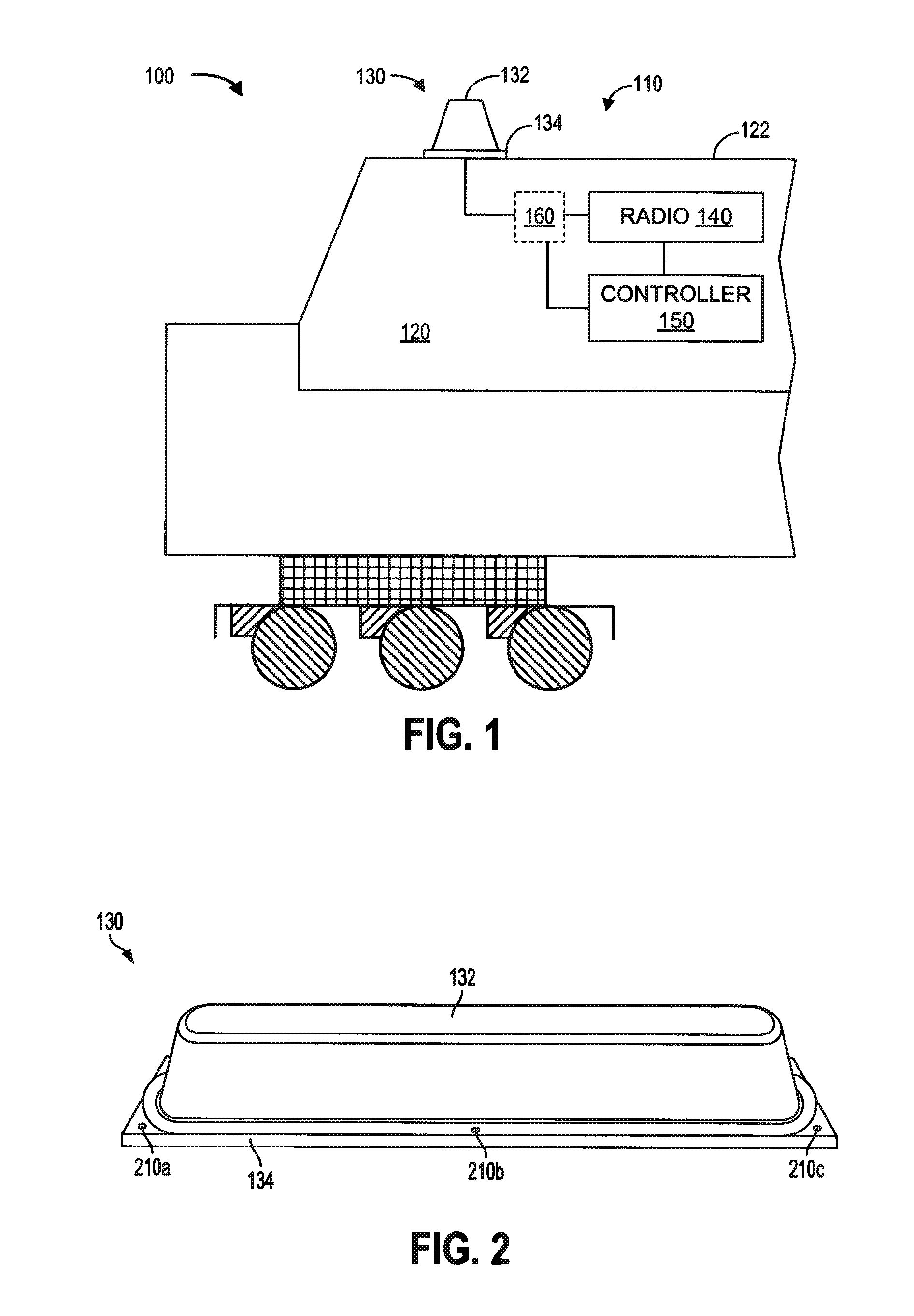
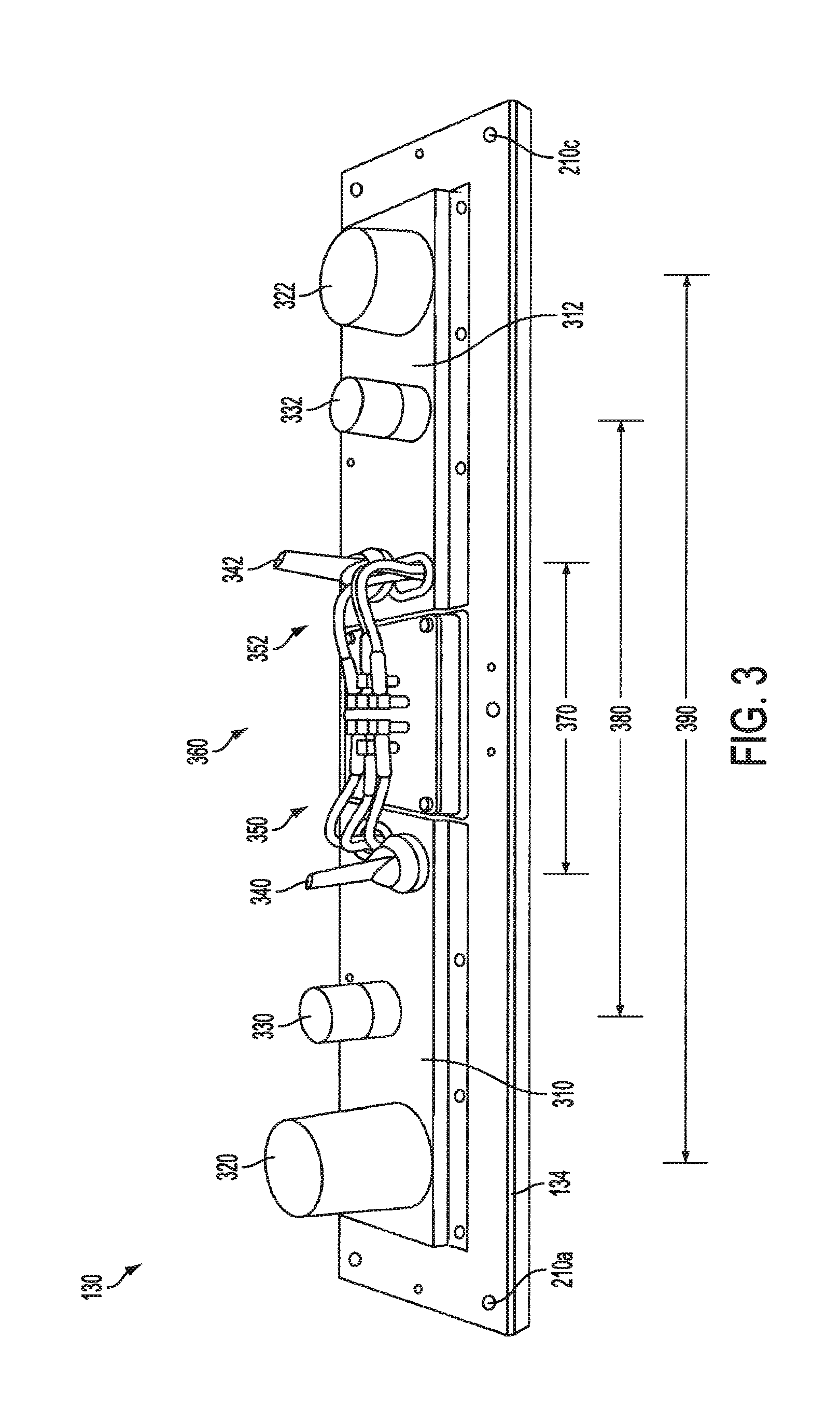
[0013]FIG. 1 illustrates an example embodiment of a vehicle, specifically, a rail vehicle such as a locomotive, comprising a radio communication system including one or more radios using one or more antennas. An antenna may be mounted on a common antenna platform which may be attached to a roof of the locomotive. The antenna may be connected to a radio in a cab of the locomotive by an antenna interface mounted to the roof of the locomotive. The antenna platform may include an antenna dome that may protect the antenna and the antenna interface from the environment. FIG. 2 shows a view of an example embodiment of the antenna platform including an antenna dome. FIG. 3 shows a view of an example embodiment of the antenna platform with the antenna dome removed. The antenna platform may include a plurality of antennas that are connected to an antenna interface. FIG. 4 shows an example embodiment of cabling between antennas and the antenna interface, and FIG. 5 shows an example embodiment ...


PUM


Abstract

In one embodiment, a radio communication system comprises a removable antenna platform and an antenna interface bulkhead connected to a roof of a locomotive. The antenna platform includes a blind mate connector connected to an antenna mount. The antenna mount is connected to a ground plane. The antenna interface bulkhead includes a blind mate connector configured to mate with the blind mate connector of the antenna platform when the antenna platform is attached to the antenna interface bulkhead. The antenna interface bulkhead is configured to attach to the antenna platform in one orientation. Thus, one or more antennas may be quickly attached to or removed from the roof of the locomotive reducing maintenance time for the locomotive when an antenna upgrade may be desired.

Description

FIELD[0001]The subject matter disclosed herein relates to an apparatus for locomotive radio communications.BACKGROUND[0002]A locomotive or other rail vehicle may be equipped with a radio communication system including a radio in a cab of the locomotive and an antenna mounted on a roof of the locomotive. The radio communication system may include one or more radios using one or more antennas, such as when transmitting and receiving voice and data communications with different radios. The configuration of radio communication systems may change during the lifetime of a locomotive due to technological or regulatory concerns. For example, the radio communication system may be regulated by a governmental agency and the regulations may change. As another example, it may be desirable to add a new radio and / or antenna as radio technology improves or if new radio spectrum becomes available. Thus, radios and their associated antennas may be added and / or removed during the lifetime of the locom...

Claims


Application Information

Patent Timeline
Patent Type & Authority Applications(United States)
IPC IPC(8): H01Q1/32H01Q1/50
CPCH01Q1/088H01Q1/3275H01Q1/1221
Inventor CORWIN, ROBERT MARKCAFFERTY, GERARDOPALKA, TIMOTHY JOHN
Owner GE GLOBAL SOURCING LLC
Why Eureka
Try Eureka