
Set of twin wheels

Inactive Publication Date: 2011-11-24
TIRE TRADE DK
View PDF13 Cites 10 Cited by
  • Summary
  • Abstract
  • Description
  • Claims
  • Application Information

AI Technical Summary

Benefits of technology

[0010]The clamping ring may hereby be more or less loose relative to the rim of the twin wheel. The tightness by which the clamping ring fits against the rim of the twin wheel may be adjustable, as the clamping ring may be with an external circumference which is adjustable, preferably by one or more adjusting screws. By using a loose clamping ring, there is achieved the advantage that the clamping ring can be used for different rim widths, and in some cases for different rim diameters, e.g. 28″ and 30″ rims, and hence the stock at the producer can be minimised while at the same time many advantages are achieved by using modular elements.
[0011]By using the outer side of the rim for contact with the clamping ring, there is achieved independency of welding such means thereon to which clamping devices are to be fixed on the twin wheel itself By using a clamping ring which is not fixed to the twin wheel, a kind of universal clamping ring can be applied which possibly may be adapted to different sizes of twin wheels, and which therefore implies less need for keeping may different articles in stock at the producer or the sales outlet. By making the mentioned clamping ring in a neutral colour, e.g. in galvanised steel, there is achieved the advantage that a clamping ring, which does take up much space, can be used together with rims painted in a colour that fit the vehicle on which the twin wheel is to be mounted, without disturbing the overall impression.
[0014]In another variant of a twin wheel set according to the invention, twin wheel and intermediate ring are capable of being separated. Hereby is also achieved the possibility of avoiding welds between rim and intermediate ring. Hereby is achieved the great advantage that the intermediate ring can be replaced by a wider or narrower intermediate ring. It is thus possible to adapt the spacing between twin wheel and vehicle wheel with regard to specific needs. At the same time, this provides the possibility of reduced stock, as intermediate rings and rims may be paired freely. For example, it may be wanted that there is a small spacing between the wheels when working the soil, while there is a wish for a given spacing between the wheels by other work, e.g. where fields with crops in rows are treated and to which the wheel spacing is to be adapted. These intermediate rings may advantageously be made in widths of 50 mm steps, e.g. widths of 150, 200, 250, 300, 350, 400, 450 mm or more, depending on the actual rim design.

Problems solved by technology

However, typically it appears that this large stock is not attractive for the supplier as orders for making twin wheels that are not in stock occur anyway.
Moreover, it is obviously a drawback with too large stock with rims adapted for specific needs.

Method used


Image

  • Set of twin wheels
  • Set of twin wheels
  • Set of twin wheels

Examples


Embodiment Construction

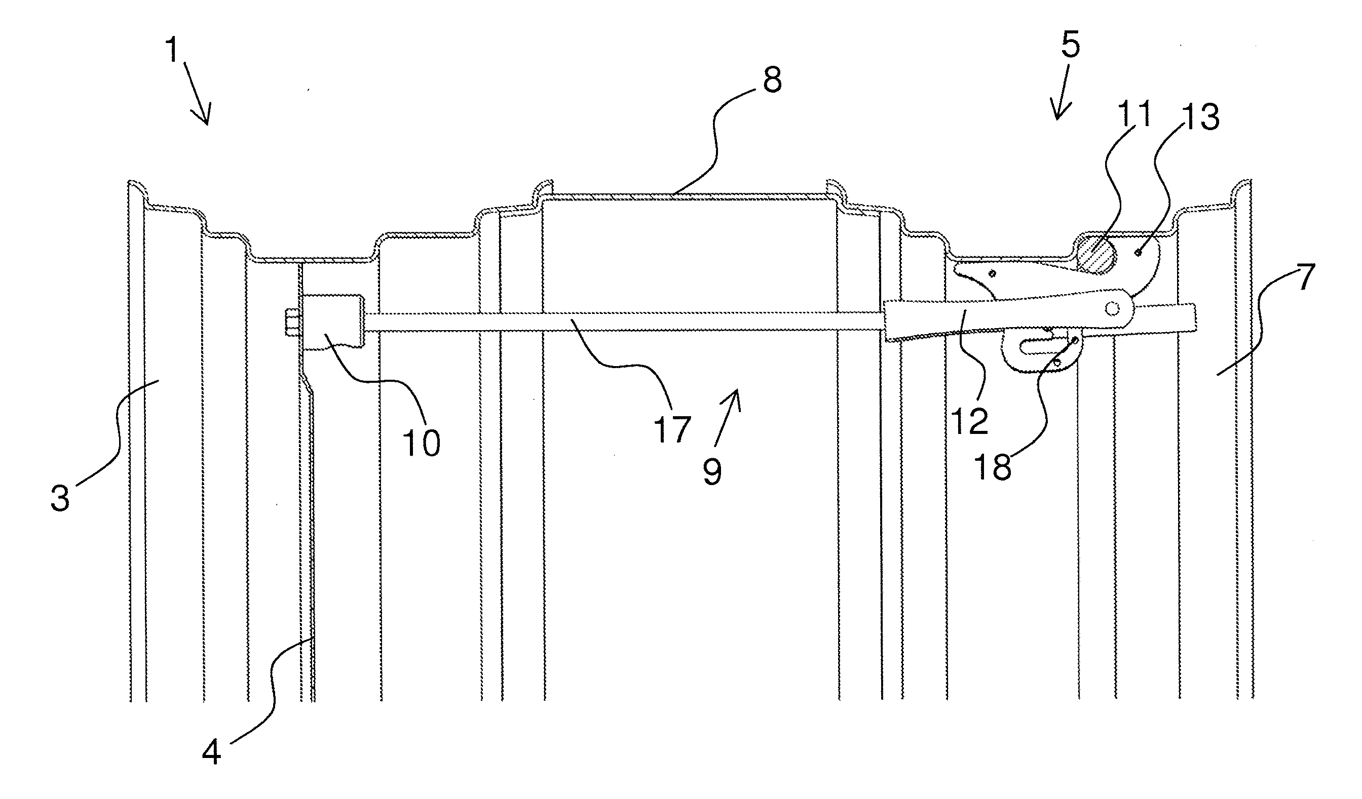
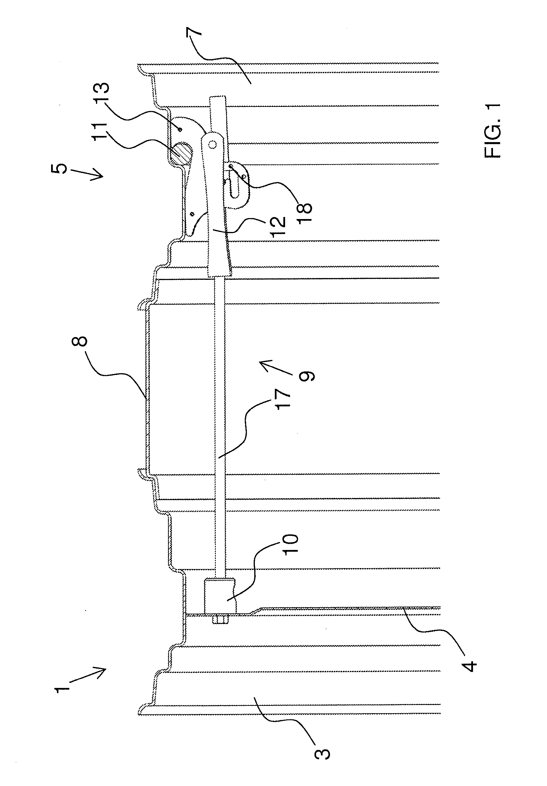
[0023]In FIG. 1 appears a cross-section of a twin mounting consisting of a vehicle wheel 1 without tyres, with rim 3 and with rim plate 4, and of a twin wheel 5, also with rim 7. Between the two rims 3 and 7 appears an intermediate ring 8.

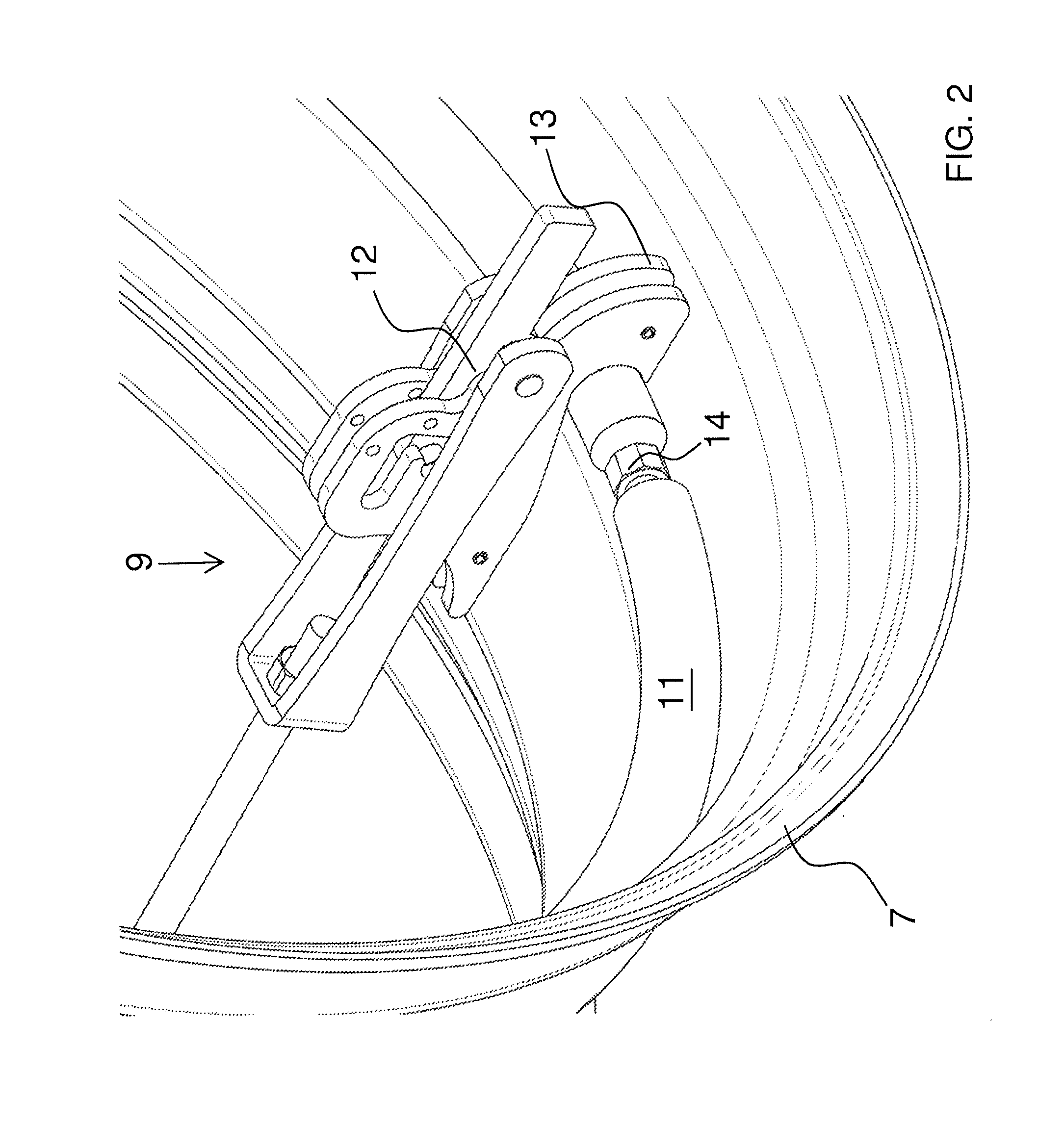
[0024]The two rims 3 and 7 are held clamped together with several clamping devices 9, but here is only shown one of them. At one end, the clamping device 9 is fixed to an anchor 10 which is fastened to the rim plate 4 and at the other end to a clamping ring 11 which bears against the rim 7 of the twin wheel at the outward facing side of the latter. The clamping ring 11 is in principle a loose clamping ring 11 which is not permanently mounted by welding or similar to the rim 7. The clamping device 9 can be made in different ways, but in a preferred variant it is provided with adjustable length and with a closing device 12 with a kind of claw or clamp part 13 that ensures a secure connection to the clamping ring 11, and at the same time allows a rapi...


PUM


Abstract

The present invention concerns a twin wheel set including twin wheel, intermediate ring and fixing means for coaxial mounting of the twin wheel set on a wheel of a vehicle, where twin wheel as well as vehicle wheel include a rim, preferably a steel rim with tyre. The new feature of the invention consist of the fixing means at least comprising an adjustable clamping ring, preferably a steel ring, for bearing on the rim periphery of the twin wheel at the side facing away from the vehicle wheel, preferably against at least one face on the inner peripheral area of the rim on a twin wheel. By using the outer side of the rim for contact with the adjustable clamping ring, there is achieved an independency of welding means thereon to which clamping devices are to be fixed on the twin wheel itself. By using a clamping ring which is not fixed to the twin wheel, a kind of universal clamping ring can be applied which possibly may be adapted to different sizes of twin wheels, and which therefore implies less need for keeping may different articles in stock at the producer.

Description

BACKGROUND OF THE INVENTION[0001]1. Field of the Invention[0002]The present invention concerns a twin wheel set, including twin wheel, intermediate ring and fixing means for coaxial mounting of the twin wheel set on a wheel of a vehicle, where the twin wheel as well as the vehicle wheel include a rim, preferably a steel rim with tyre, where the fixing means at least include a clamping ring, preferably a steel ring, for bearing against the rim periphery of the twin wheel at the side facing away from the vehicle wheel, preferably against at least one face of the inner peripheral area of the rim on a twin wheel.[0003]2. Description of Related Art[0004]It is commonly known that in industry and farming, twin mounted wheels are used, i.e. an additional wheel mounted on each of the original wheels of the vehicle in question. The purpose of twin wheels is to distribute the load from the vehicle across a larger area and at the same time achieve a better grip in the base for the drive wheels ...

Claims


Application Information

Patent Timeline
IPC IPC(8): B60B11/02
CPCB60B11/02
Inventor RATGEN, FELIX PALUDAN
Owner TIRE TRADE DK
Learn More