Rim system for a display

Inactive Publication Date: 2010-03-04
TP VISION HLDG B V HOLDCO
View PDF9 Cites 43 Cited by
  • Summary
  • Abstract
  • Description
  • Claims
  • Application Information

AI Technical Summary

Benefits of technology

[0045]In that way, the light detected at the periphery on the display and the ambience will be converted directly into the light guide, thereby allowing a smo

Problems solved by technology

This can easily result in tire

Method used


Image

  • Rim system for a display
  • Rim system for a display
  • Rim system for a display

Examples


Embodiment Construction

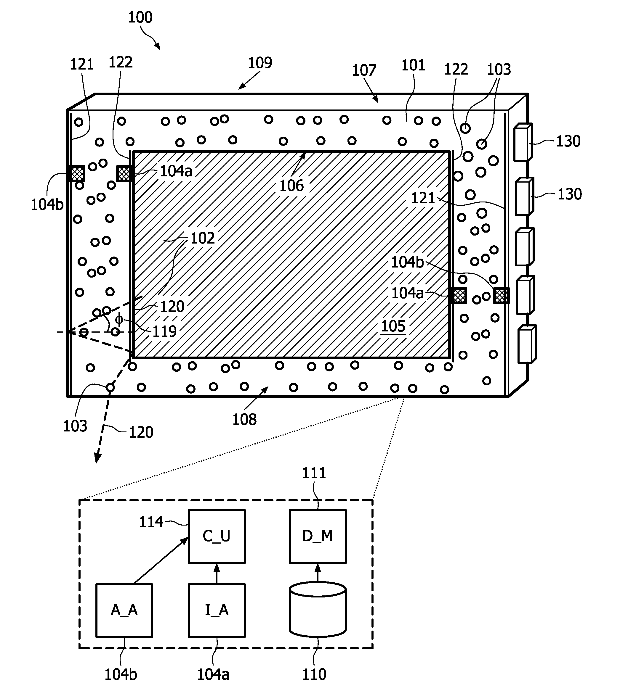
[0063]FIG. 1 shows a rim system 100 for a display 105, e.g. LCD or PDP, comprising at least one controllable light source 102 adapted for emitting a light beam 120 of at least one wavelength, a light guide 101 comprising an inner 106 and an outer side 107 and a front 108 and a back side 109 adapted for guiding incoming light emitted by the light sources 102. This light guide 101 comprises an out-coupling structure 103 for interacting with the light guided within the light guide 101 such that the light becomes extracted out of the front side 108 of the light guide 101. In one embodiment, the out-coupling structure is selected from the group of an array of dots of white paint and / or an array of grooves. The at least one controllable light source is coupled to the light guide such that the light beam 120 emitted by the light sources 102 reaching the inner 106 and / or the outer sides 107 from within the light guide 101 becomes reflected under an oblique angle 119 with respect to the inne...


PUM


Abstract

This invention relates to a rim system for a display such as a TV or a computer display. Controllable light sources are used for emitting light beam of at least one wavelength into a light guide comprising an inner and an outer side and a front and a back side, the light guide being adapted for guiding incoming light emitted by the light sources. The light guide 5 comprises an out-coupling structure for interacting with the light guided within the light guide such that the light becomes extracted out of the front side of the light guide. The light sources are coupled to the light guide such that the emitted light beam reaching the inner and the outer sides from with hin the light guide becomes reflected under an oblique angle with the respect to the inner and the outer sides.

Description

FIELD OF THE INVENTION[0001]The present invention relates to a rim system for a display, and to a display system comprising the rim system attached to the periphery of the display system.BACKGROUND OF THE INVENTION[0002]Ambilight is a concept that enhances the viewing experience when watching TV by applying ambient lighting in order to extend the image outside the boundaries of the TV screen. This concept has been introduced in the market recently and found to have a tremendous positive impact on the sales of high-end LCD's equipped with this feature.[0003]In the Ambilight concept, as it is implemented at present, by means of e.g. low-pressure gas-discharge lamps such as CCFL (cold-cathode-fluorescence) lamps located behind the TV set, an extension of the image is projected on the wall behind the TV. Each lamp can be considered to create a ‘pixel’ of light on the wall behind the display (or on a dedicated diffusely reflecting or diffusely transmitting screen attached to the display)...

Claims


Application Information

Patent Timeline
IPC IPC(8): G09G5/10H05B37/02
CPCF21V33/0052F21Y2101/02G02B6/0038H04N5/64G02B6/0055G02B6/0068G02B6/0041F21Y2115/10
Inventor KRIJN, MARCELLINUS PETRUS CAROLUS MICHAELSALTERS, BART ANDREHOOGENSTRAATEN, WILLEM FRANCISCUS JOHANNES
Owner TP VISION HLDG B V HOLDCO
Why Eureka
Try Eureka