Vibration Exciter For A Ground Compactor And Ground Compactor

a technology of vibration exciter and ground compactor, which is applied in the direction of gearing, soil preservation, and ways, can solve the problems of unfavorable assembling, inability to reliably ensure the turnover weight of the exciter, and the inability to distinguish the turnover weight from the exciter weight, etc., to achieve convenient rotational direction switching, less disadvantageous effect, and easy assembly

Active Publication Date: 2011-12-01
BOMAG
View PDF12 Cites 15 Cited by
  • Summary
  • Abstract
  • Description
  • Claims
  • Application Information

AI Technical Summary

Benefits of technology

[0008]As a result of this axial offset of the axes of rotation, it is possible to decisively vary the kinematic conditions so that from a certain angle of rotation, the at least one turnover weight is always pressed onto the stop on the exciter shaft or the exciter weight. By this means a distinct turning and an associated change of amplitude is ensured even if the turnover weight should recoil after the impact. The turnover weight therefore no longer adopts a neutral position. The recoil therefore has a less disadvantageous effect. Furthermore, the arrangement according to one embodiment of the present invention also facilitates the switching of the direction of rotation of the vibration arrangement.
[0009]In principle, according to one aspect of the present invention, the two axes of rotation can lie with respect to one another such that they intersect at one point or are skew with respect to one another. It is preferable however that the axes of rotation of the exciter shaft and the at least one turnover weight are oriented parallel to one another. Optimal results can be obtained with this arrangement of the two axes of rotation with respect to one another. Furthermore, this embodiment is characterised by being comparatively easy to assemble.
[0010]The axial offset of the two axes of rotation with respect to one another is further ideally selected in such a manner that its position stabilizing effect on the positioning of the turnover weight with respect to the exciter weight has almost the same effect on the two outer adjustment positions. According to a further development it is therefore provided that the axis of rotation of the at least one turnover weight is offset relative to the axis of rotation of the exciter shaft or the exciter weight by a defined value, where this value is measured as the inward-pointing distance on the angle bisector of the turning angle. The specific geometrical relationships of this embodiment will be explained in further detail hereinafter in connection with the figures.
[0011]The axial offset can fundamentally be varied in a wide range. The positive effect of the present invention appears however even with a relatively small axial offset. A comparatively small axial offset additionally has the advantage that the vibration exciter according to the present invention can be kept compact in its manner of construction as previously. Exceptional results are accordingly achieved if the distance of the axes of rotation on the angle bisector lies in the range of a few millimeters and preferably in the range of 1 mm to 15 millimeters and especially in the range of 1.5 to 10 millimeters, quite particularly in the range of 2 to 5 millimeters. The distance is measured in this case in the plane which is intersected perpendicularly by at least the axis of rotation of the exciter shaft. In particular, in this embodiment it is ideal if the two axes of rotation lie parallel to one another and consequently both intersect this plane perpendicularly. If the two axes of rotation do not run parallel to one another, the offset is determined from the shortest distance of the two axes of rotation to one another.

Problems solved by technology

A disadvantage in the vibration exciters known from the prior art in particular is the uncontrolled recoil of the turnover weights upon impact.
Another and frequently associated disadvantage is that frequently no distinct turnover of the turnover weight takes place.
As a result, for example, the position in which the turnover weight adds to the exciter weight cannot be reliably ensured or the maximum amplitude of the exciter unit cannot be achieved.
As a result, the maximum compaction performance of the compactor cannot be provided.

Method used


Image

  • Vibration Exciter For A Ground Compactor And Ground Compactor
  • Vibration Exciter For A Ground Compactor And Ground Compactor
  • Vibration Exciter For A Ground Compactor And Ground Compactor

Examples


Embodiment Construction

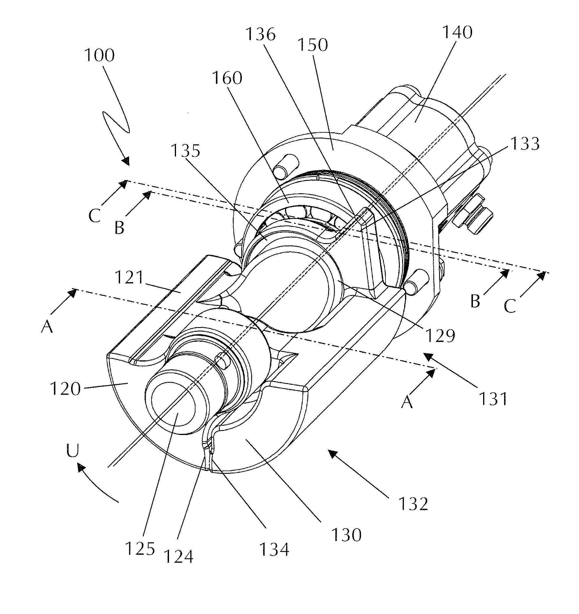
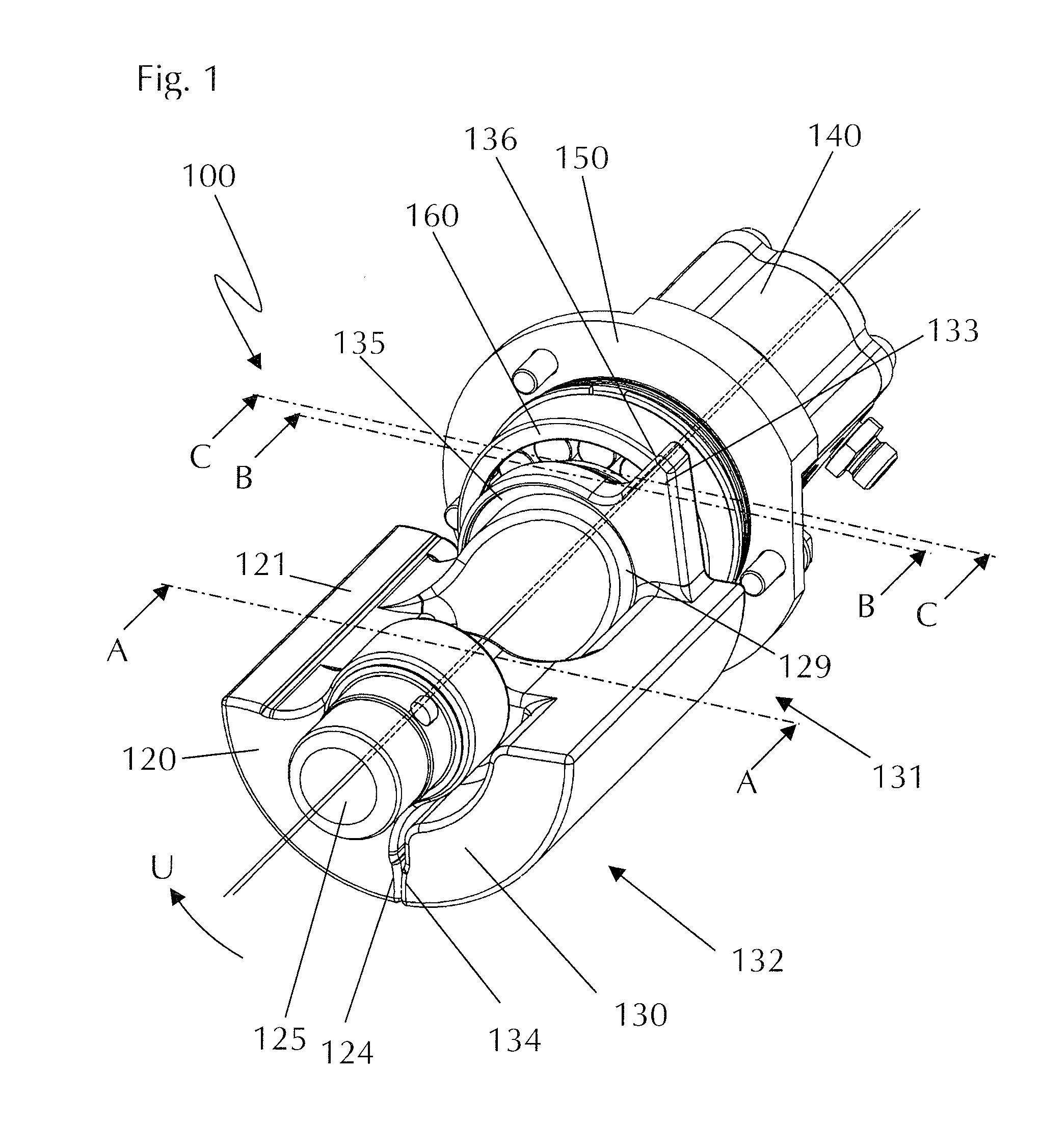
[0032]FIG. 1 shows a vibration exciter 100 according to one embodiment of the present invention in a perspective view. The vibration exciter 100 comprises an exciter weight 120 which is formed in one piece with a partially visible exciter shaft 110 and a turnover weight 130. The exciter weight 120 and the exciter shaft 110 together form a structural unit. The vibration exciter 100 further comprises a motor 140, wherein in the present exemplary embodiment this specifically comprises a hydraulic motor. The motor 140 is coupled onto the exciter shaft 110 in alignment. The common axis of rotation is designated by Dg. The exciter weight 120 or the exciter mass 120 are disposed eccentrically with respect to this axis of rotation Dg so that during rotation about the axis of rotation Dg in the desired manner, useful vibrations are produced. On the side opposite the motor 140, the exciter shaft 110 with a bearing journal 125 projecting in the axial direction (along Dg) is received in a beari...


PUM


Abstract

A vibration exciter for a ground compactor comprises an exciter shaft having at least one exciter weight disposed thereon and having at least one turnover weight which is disposed so that it can rotate relative to this exciter shaft. The present invention further relates to a ground compactor having such a vibration exciter.

Description

FIELD OF THE INVENTION[0001]The present invention relates to a vibration exciter (or an apparatus for exciting vibrations) for a ground compactor. The present invention further relates to a ground compactor having at least one such vibration exciter.BACKGROUND OF THE INVENTION[0002]A generic vibration exciter, as well as a ground compactor equipped therewith, are known, for example, from U.S. Pat. No. 7,059,802 B1. In order to improve the compacting action of the ground compactor shown, the compacting rollers are exposed to vibrations in compacting operation. The vibrations are generated by one (or by a plurality of) vibration exciters. A vibration exciter comprises an exciter shaft driven rotationally about an axis of rotation, on which a so-called exciter weight (exciter mass) is disposed eccentrically. In the following, “exciter weight” designates the structural entirety of exciter weight and exciter shaft unless otherwise specified. Vibrations which can be used for compaction ar...

Claims


Application Information

Patent Timeline
Patent Type & Authority Applications(United States)
IPC IPC(8): E02D3/074
CPCY10T74/18552E02D3/074E01C19/286Y10T74/18544Y10T74/18344
Inventor STEIN, GILBERTDYKHNICH, ALEXANDER
Owner BOMAG
Why Eureka
Try Eureka