Light emitting device, planar light source, and display device

a technology of light emitting devices and planar light sources, applied in the direction of semiconductor devices, basic electric elements, electrical apparatus, etc., can solve the problem of limiting the efficiency of obtaining light from the sidewall, and achieve the effect of little unevenness in illuminance and chromaticity

Active Publication Date: 2011-12-01
XIAMEN SANAN OPTOELECTRONICS CO LTD
View PDF3 Cites 34 Cited by
  • Summary
  • Abstract
  • Description
  • Claims
  • Application Information

AI Technical Summary

Benefits of technology

[0023]The light emitting device of the present invention includes: a substrate; at least one semiconductor light emitting element die-bonded to the substrate; a sealing material covering said at least one semiconductor light emitting element, four planes uprising from the substrate, and a lens having a ceiling surface facing the substrate, the four planes being positioned in four directions, respectively, in such a manner as to surround said at least one semiconductor light emitting element, the ceiling surface having a concave portion, and emission of light from the light emitting device forming, on a view plane parallel to the substrate, a contour of an illumination shape which is a rectangle whose corners are rounded.
[0024]The light emitting device of the present invention includes: a substrate; at least one semiconductor light emitting element die-bonded to the substrate; and a sealing material covering said at least one semiconductor light emitting element, the sealing material serving as a lens including four planes uprising from the substrate and a ceiling surface facing the substrate; the ceiling surface having a concave portion, and emission of light from the light emitting device forming, on a view plane parallel to the substrate, a contour of an illumination shape which is a rectangle whose corners are rounded.
[0025]Therefore, it is possible to provide a thin light emitting device with little unevenness in illuminance and chromaticity.

Problems solved by technology

The light traveling via the second light path P2 is not a desirable one, which limits an efficiency of obtaining light from the sidewall 35.

Method used


Image

  • Light emitting device, planar light source, and display device
  • Light emitting device, planar light source, and display device
  • Light emitting device, planar light source, and display device

Examples


embodiment 1

[0048]The following explains an embodiment of the present invention with reference to FIGS. 1-10.

[Light Emitting Device]

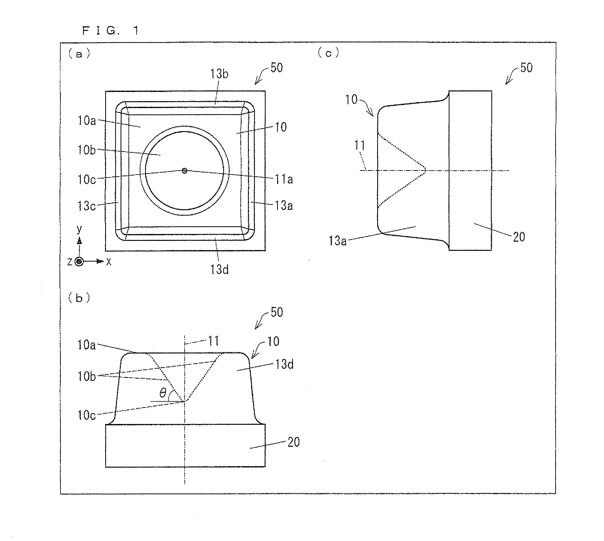
[0049]FIG. 1 is an explanatory drawing explaining a mortar-shaped or funnel-shaped light emitting device 50 in accordance with Embodiment 1 of the present invention. (a) of FIG. 1 is a plan view of the mortar-shaped or funnel-shaped light emitting device 50 in accordance with Embodiment 1. (b) of FIG. 1 is an elevation view of the mortar-shaped or funnel-shaped light emitting device 50 in accordance with Embodiment 1. (c) of FIG. 1 is a side view of the mortar-shaped or funnel-shaped light emitting device 50 in accordance with Embodiment 1.

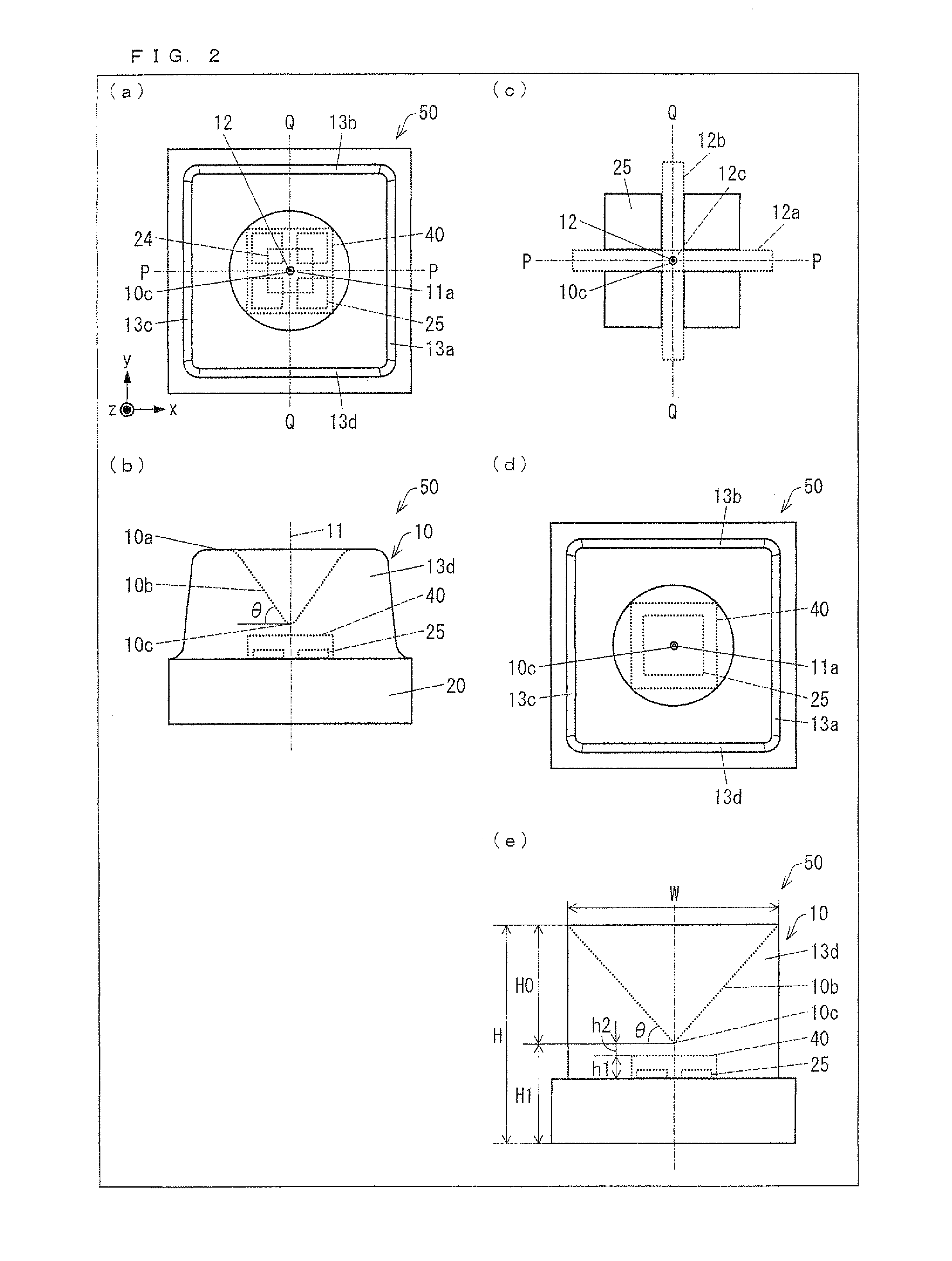
[0050]FIG. 2 is an explanatory drawing explaining the mortar-shaped or funnel-shaped light emitting device 50 in accordance with Embodiment 1. (a) of FIG. 2 is a plan view showing an inner structure of the mortar-shaped or funnel-shaped light emitting device 50 in accordance with Embodiment 1. (b) of FIG. 2 is an elevation view s...

embodiment 2

[0122]The following explains another embodiment of the present invention with reference to FIGS. 11-14. Arrangements other than arrangements explained in the present embodiment are the same as those in Embodiment 1. For convenience of explanation, members having the same functions as those shown in the drawings of Embodiment 1 are given the same reference numerals and explanations thereof are omitted here.

[0123]FIG. 11 shows a plan view, an elevation view, and a side view of a wedge-shaped light emitting device 80 in accordance with Embodiment 2. FIG. 12 shows an internal structural view of the wedge-shaped light emitting device 80. FIG. 13 shows views indicating a light distribution property and an illumination shape, respectively, of the wedge-shaped light emitting device 80. The following explains the wedge-shaped light emitting device 80 in accordance with Embodiment 2 in terms of differences from the mortar-shaped or funnel-shaped light emitting device 50 in accordance with Emb...

embodiment 3

[0142]The following explains another embodiment of the present invention with reference to FIGS. 15 and 16. Arrangements other than arrangements explained in the present embodiment are the same as those in Embodiments 1 and 2. For convenience of explanation, members having the same functions as those shown in the drawings of Embodiments 1 and 2 are given the same reference numerals and explanations thereof are omitted here.

[0143]FIG. 15 shows plan views and an elevation view of a light emitting device 90 in accordance with Embodiment 3. FIG. 16 shows illumination shapes in Embodiment 3.

[0144](a) of FIG. 15 is a plan view of the light emitting device 90 in accordance with Embodiment 3. (b) of FIG. 15 is an elevation view of the light emitting device 90 in accordance with Embodiment 3. (c) of FIG. 15 is an enlarged view of an LED chip and its surroundings in the light emitting device 90 in accordance with Embodiment 3. (d) of FIG. 15 is a plan view showing a configuration in which one...


PUM


Abstract

A mortar-shaped or funnel-shaped light emitting device (50) includes: a substrate (20); at least one LED chip (25) die-bonded to the substrate (20); and a wavelength converting portion (40) covering said at least one LED chip (25); at least four planes uprising from the substrate (20); and a lens having a top surface (10a) facing the substrate (20), the four planes being positioned in four directions, respectively, in such a manner as to surround said at least one LED chip (25), and the top surface (10a) having a concave portion.

Description

TECHNICAL FIELD[0001]The present invention relates to: a light emitting device having a sealing material for directing emitted light to a predetermined direction; a planar light source in which a plurality of the light emitting devices are arranged; and a display device including the planar light source.BACKGROUND ART[0002]Some liquid crystal display devices include, as backlights for illuminating liquid crystal display panels from backsides, planar light sources in which light sources such as LEDs (Light Emitting Diodes) are arranged. Such a backlight is different from an edgelight-type backlight using a light guide plate in that such a backlight illuminates a liquid crystal display panel from the backside without using a light guide plate. Such a backlight is referred to as a direct-type backlight.[0003]Light sources used in the direct-type backlight are required to be reduced in number in order to reduce costs, and therefore a wider light distribution property is required. Some L...

Claims


Application Information

Patent Timeline
Patent Type & Authority Applications(United States)
IPC IPC(8): H01L33/50H01L33/60
CPCH01L25/0753H01L33/54H01L33/58H01L2924/0002H01L2924/00
Inventor ITO, SHIN
Owner XIAMEN SANAN OPTOELECTRONICS CO LTD
Why Eureka
Try Eureka