
Imaging apparatus, imaging system, and imaging apparatus control method and program

a technology of imaging apparatus and control method, applied in the field of imaging apparatus, can solve the problems of reducing the size or reducing of the live preview picture, making the live preview picture more difficult to see, etc., and achieve the effect of suitable focus control, excellent advantages, and maintaining visibility

Active Publication Date: 2011-12-01
SONY CORP
View PDF5 Cites 19 Cited by
  • Summary
  • Abstract
  • Description
  • Claims
  • Application Information

AI Technical Summary

Benefits of technology

The present invention provides an imaging apparatus and control method that can improve focus control during live preview display while maintaining visibility. This is achieved by setting a focus lens movement range based on the imaging magnification and the rate of change in imaging magnification. By doing so, the live preview picture can be enlarged or reduced without affecting the user's ability to see or confirm the subject. The invention also allows for the setting of a movement range based on the focal depth and the position of the focus lens, or in the case of an interchangeable lens, based on the imaging magnification and the state of the optical members. The invention can be implemented in an imaging system with an interchangeable lens and an imaging apparatus.

Problems solved by technology

However, in the case where the rate of change in the imaging magnification is comparatively large, the enlargement or reduction of a live preview picture becomes great, and may make a live preview picture more difficult to see when the user confirms a subject.

Method used


Image

  • Imaging apparatus, imaging system, and imaging apparatus control method and program
  • Imaging apparatus, imaging system, and imaging apparatus control method and program
  • Imaging apparatus, imaging system, and imaging apparatus control method and program

Examples


first embodiment

1. First Embodiment

[Exemplary Internal Configuration of Imaging System]

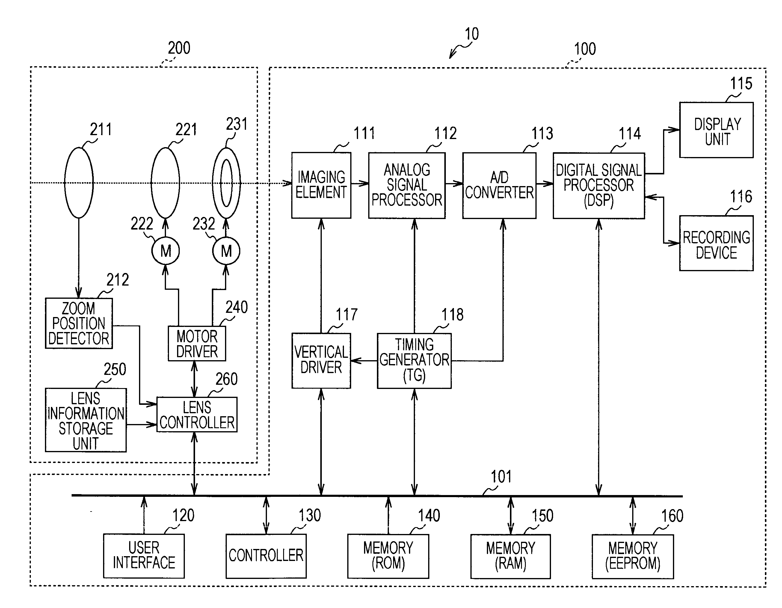
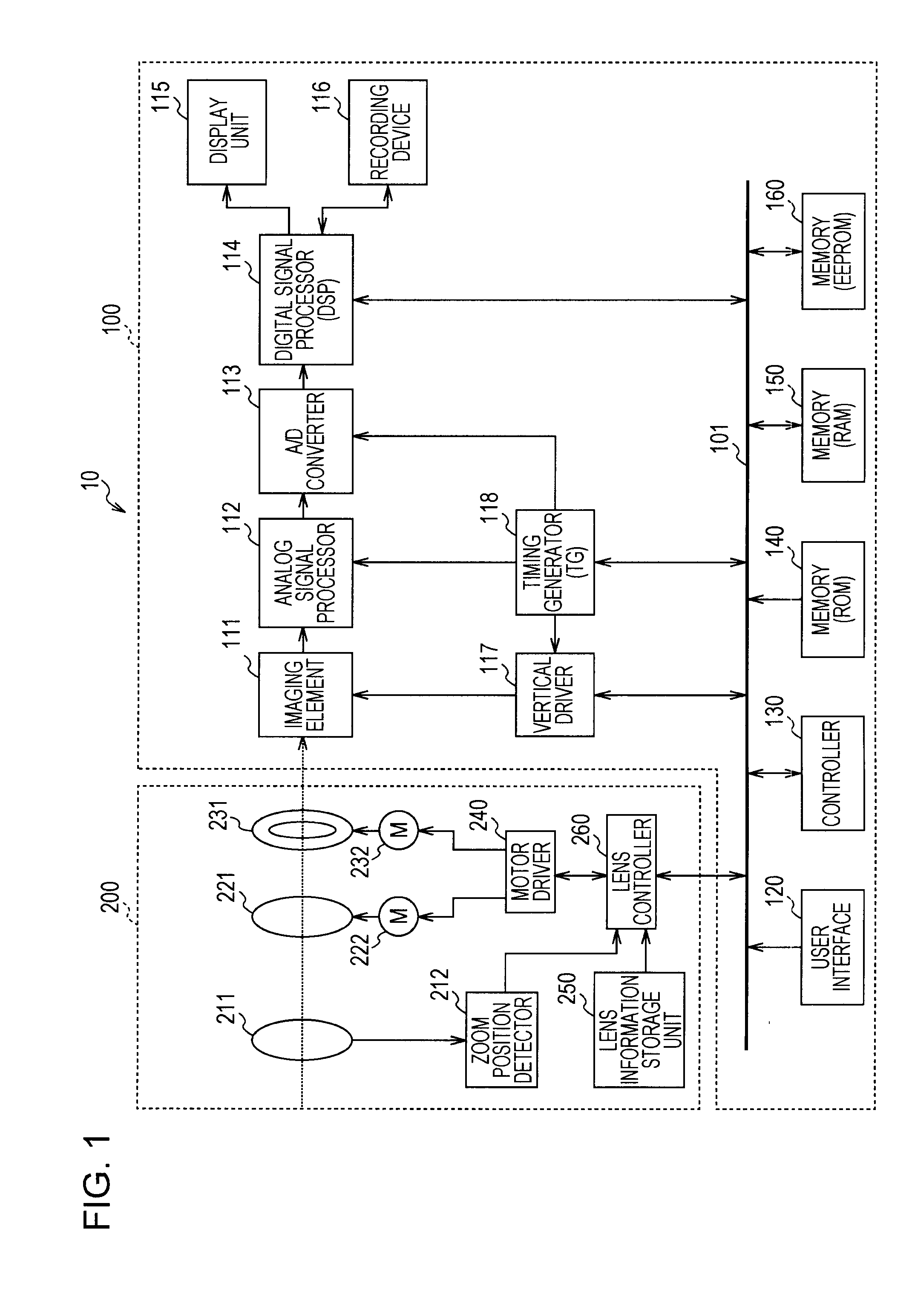
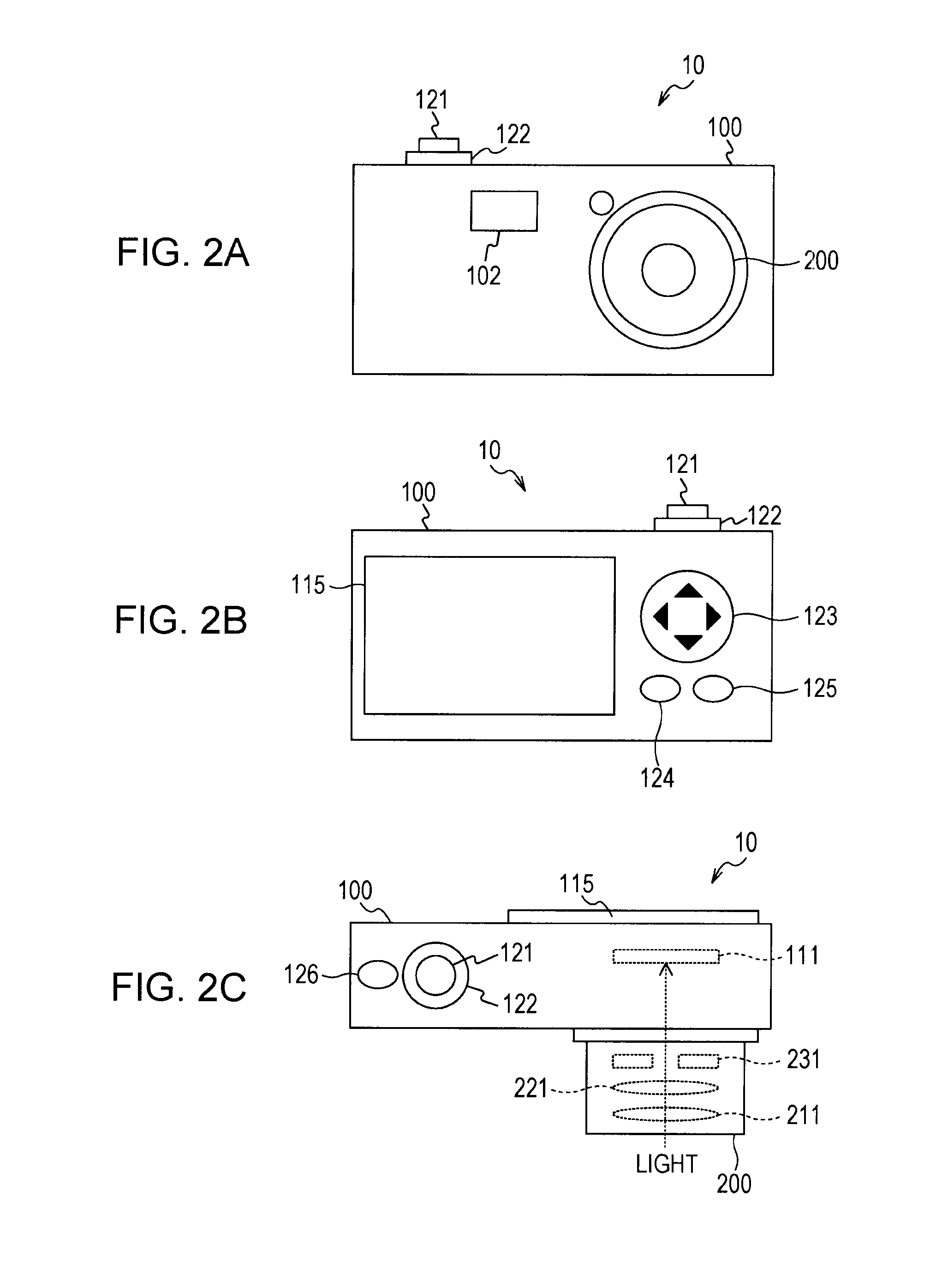
[0034]FIG. 1 is a block diagram illustrating an exemplary internal configuration of an imaging system 10 in accordance with a first embodiment of the present invention. The imaging system 10 is provided with an imaging apparatus 100 and an interchangeable lens 200. The imaging system 10 is realized by, for example, a digital still camera in which the lens can be interchanged (a digital single-lens camera, for example).

[0035]The imaging apparatus 100 images a subject and generates picture data (an imaged picture), and records generated picture data as picture content (still picture content or motion picture content). Also, an interchangeable lens 200 may be attached to the imaging apparatus 100 via a lens mount (not illustrated).

[0036]The interchangeable lens 200 is an interchangeable lens unit attached to the imaging apparatus 100 via a lens mount (not illustrated). The interchangeable lens 200 is provided with a...

second embodiment

2. Second Embodiment

[0152]In a first embodiment of the present invention, an example of setting a focus lens movement range on the basis of imaging magnification when fixed conditions are satisfied was illustrated for an imaging system 10 wherein a removable, interchangeable lens 200 is attached to an imaging apparatus 100. However, a first embodiment of the present invention may also be applied to an imaging apparatus such as a digital still camera with an integrated lens, for example. Thus, in a second embodiment of the present invention, an example of setting a focus lens movement range on the basis of imaging magnification when fixed conditions are satisfied will be described for an imaging apparatus with an integrated lens. Herein, the configuration of an imaging apparatus in accordance with a second embodiment of the present invention is mostly similar to the examples illustrated in FIGS. 1 to 3. For this reason, like reference numbers are given to parts shared in common with ...


PUM


Abstract

In an imaging apparatus, an imager generates an imaged picture by converting incident light from a subject that is incident via a focus lens. A setting unit sets, as a movement range for the focus lens, a range of focus lens positions corresponding to imaging magnifications where the rate of change in the imaging magnification lies within a fixed range from a basis, the basis being an imaging magnification corresponding to the position of the focus lens. A focus controller configured to conduct focus control with respect to the subject by moving the focus lens in the set movement range.

Description

BACKGROUND OF THE INVENTION[0001]1. Field of the Invention[0002]The present invention relates to an imaging apparatus, and more particularly, to an imaging apparatus and imaging system provided with autofocus functions, a method for controlling the same, and a program that causes a computer to execute the method.[0003]2. Description of the Related Art[0004]Recently, imaging apparatus such as digital still cameras and digital video cameras (camcorders, for example) are becoming popular. Such imaging apparatus image a person, animal, or other subject to generate picture data (an imaged picture), and record this picture data as picture content. There also exist imaging apparatus that display an imaged picture generated by an imaging element on a display unit as a live preview picture while in an imaging standby state in the case of shooting a still picture, for example. By displaying a live preview picture in this way, the user is able to easily confirm his or her desired angle of view...

Claims


Application Information

Patent Timeline
Patent Type & Authority Applications(United States)
IPC IPC(8): H04N5/232
CPCG02B7/102H04N5/23212G03B13/36H04N23/959H04N23/673H04N23/63
Inventor TERASHIMA, YOSHITOISHIWATA, HISASHI
Owner SONY CORP
Learn More