LED luminaire

Inactive Publication Date: 2011-12-01
LITE ON TECH CORP +1
View PDF2 Cites 30 Cited by
  • Summary
  • Abstract
  • Description
  • Claims
  • Application Information

AI Technical Summary

Benefits of technology

[0009]The present invention offers the following advantages. The body portion and the optical structure could be made by the same or different plastic material. Next, a co-extrusion process could be used to produce the body portion and the optical structure integrally. No additional assembly is needed, which increa

Problems solved by technology

The viewers may feel uncomfortable in vision due to the hot spot phenomenon.
However, the probl

Method used


Image

  • LED luminaire
  • LED luminaire
  • LED luminaire

Examples


first embodiment

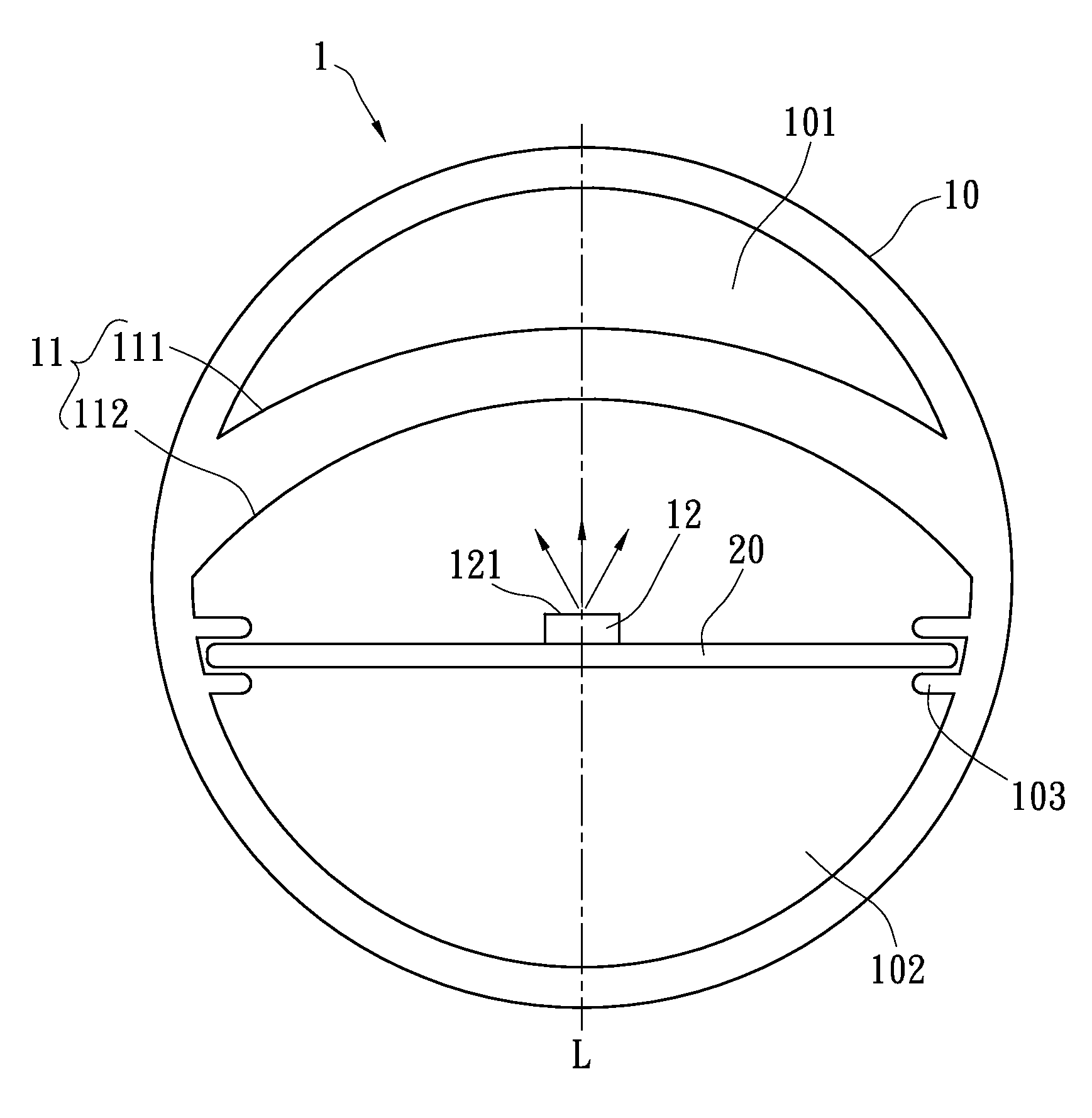
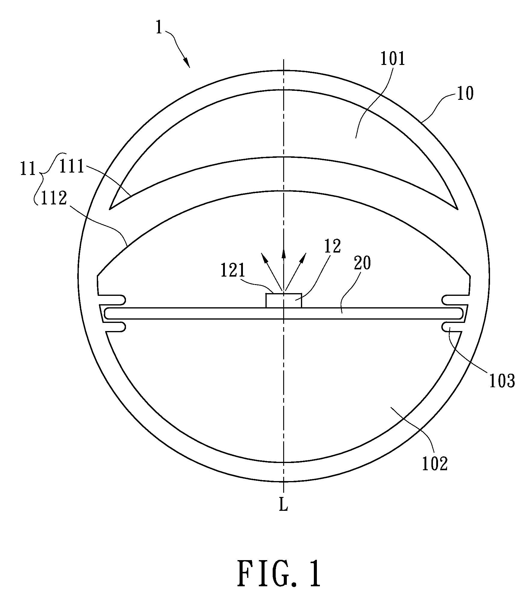
[0024]Please refer to FIG. 1; the LED luminaire 1 of the first embodiment is shown, and the LED luminaire 1 at least has a body portion 10 and an optical structure 11. A lighting module 12, for example a LED chip, is located in the body portion 10. In the present embodiment, the lighting module 12 may be fixed on the upper surface of a heat-dissipating element 20. The heat-dissipating element 20 may be formed by an aluminum-extrusion method and is used for dissipating heat generated from the lighting module 12. In addition, the heat-dissipating element 20 may be electrically connected to different circuit boards (not shown), for example, a LED control circuit board or a drive circuit board, and the circuit boards may be mounted on the heat-dissipating element 20. Therefore, the heat-dissipating element 20 is further provided for dissipating heat generated from the circuit boards.

[0025]The optical structure 11 is formed integrally with the body portion 10. For example, the extrusion ...

second embodiment

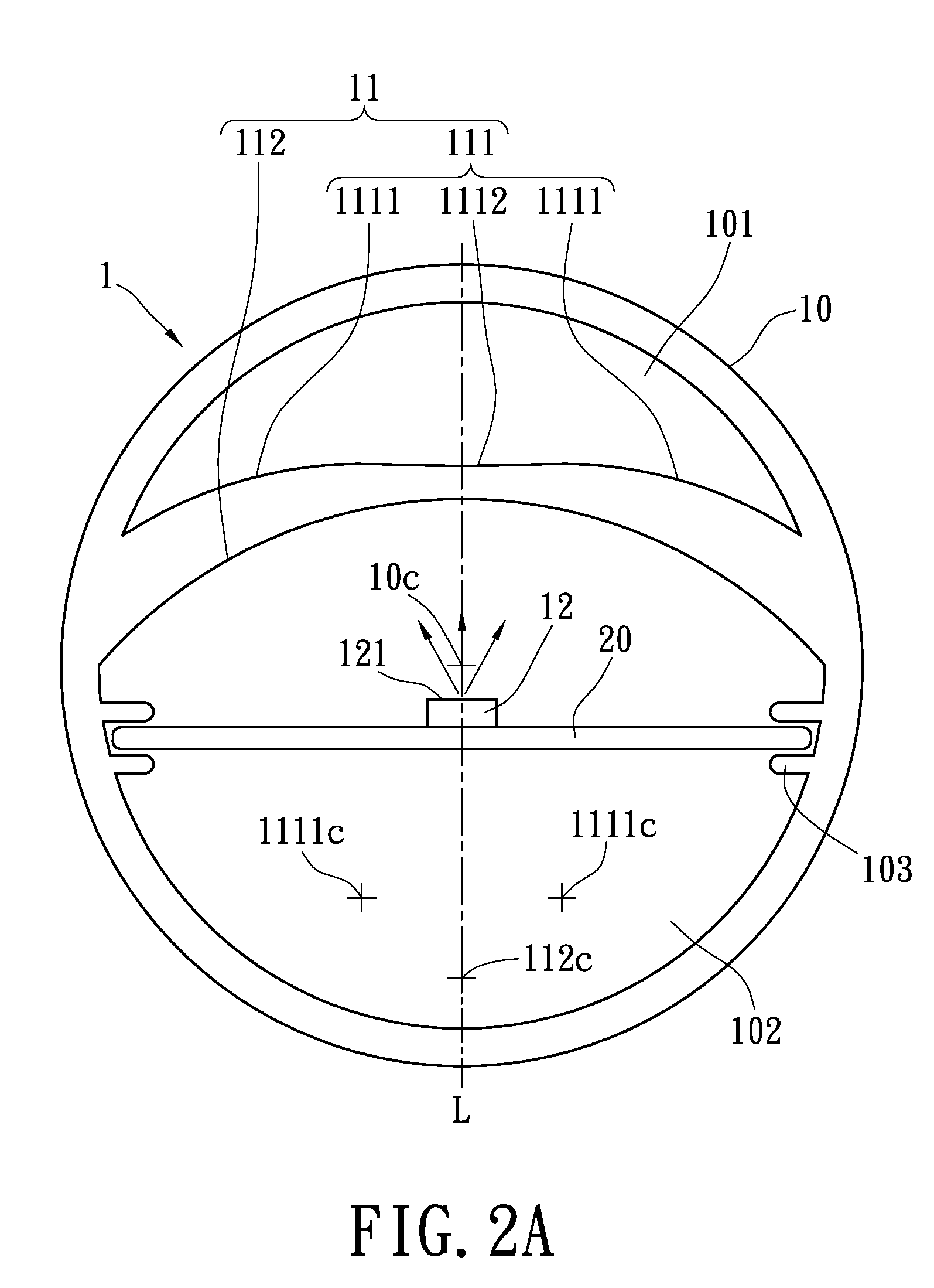
[0029]Please refer to FIG. 2A again. For the present invention, the second surface 112 of the optical structure 11 has a circular center 112C and the body portion 10 has a circular center 10C (i.e., a core). The circular centers 10C, 112C are coaxial and are located on the same light axis “L”. The two side portions 1111 are arc-surfaces with the same curvature but have different circular centers 1111c (i.e., two circular centers are shown in FIG. 2A). The circular centers 1111c of the two side portions 1111 are symmetric to the light axis “L,” which is coaxial with the axis defined by the circular centers 10C, 112C.

[0030]With reference to FIG. 1 and FIG. 2A, the LED luminaire 1 has two accommodating rooms thereinside. The first accommodating room 101 is constructed by the first surface 111 of the optical structure 11 and the inner surface of the body portion 10. The second accommodating room 102 is constructed by the second surface 112 of the optical structure 11 and the inner surfa...

third embodiment

[0036]Please refer to FIG. 7; the third embodiment is shown. The optical structure 11 is formed inside the body portion 10 and located in the light-projection path of the lighting module 12. The optical structure 11 substantially has a first surface 111 and a second surface 112, and the two surfaces 111, 112 are not parallel to each other. The first surface 111 consists with two side portions 1111 and a middle portion 1112 between the two side portions 1111. In the present embodiment, the optical structure 11 or the light-projecting area of the body portion 10 may have optical micro-structure thereon for improving the light uniformity. As shown in FIG. 7, the second surface 112 of the optical structure 11 has a plurality of convex portion 1121 of the optical micro-structure 112, and the convex portions 1121 may be formed integrally with the optical structure 11 and the body portion 10 by the co-extrusion method. Therefore, the view angle of the LED luminaire is increased and the con...


PUM


Abstract

A LED luminaire includes a body portion having a lighting module and an optical structure formed integrally with the body portion. The optical structure is formed within the body portion and located in a light-projection direction of the lighting module. The optical structure substantially is a sheet-like structure with a first surface and a second surface. The first surface has at least two side portions with a first curvature, and the second surface has a second curvature. The first curvature is greater than the second curvature. Thereby, the view angle of the light is increased as the light generated from the lighting module passes through the optical structure.

Description

BACKGROUND OF THE INVENTION[0001]1. Field of the Invention[0002]The present invention relates to a LED luminaire, and more particularly, to a LED luminaire with wide view angle.[0003]2. Description of Related Art[0004]LEDs are widely used in lighting application, such as in various luminaire. For example, the luminaire may be a tube, a bulb or a down light, etc.[0005]The view angle of the traditional LED is about 120 degrees. Due to the small view angle, just as the tube for example, the tube using the traditional LED module has smaller view angle than the fluorescent tube in the transverse direction perpendicular to the tube shaft. Furthermore, multiple LEDs are arranged along the tube shaft and a dark area occurs between the adjacent LEDs because of the small view angle. Therefore, the regions of high light density and low light density are occurred alternatively in the longitudinal direction of the tube shaft (i.e., hot spot). The viewers may feel uncomfortable in vision due to t...

Claims


Application Information

Patent Timeline
IPC IPC(8): F21V11/00
CPCF21K9/00F21S4/003F21V5/002F21V5/008F21V29/89F21Y2103/003F21V29/22F21V29/246F21V29/70F21Y2101/02F21S4/20F21Y2103/10F21Y2115/10
Inventor HUANG, JEN-MINLIANG, CHIH-LUNG
Owner LITE ON TECH CORP
Why Eureka
Try Eureka