

Spout member and packaging bag utilizing same
- Summary
- Abstract
- Description
- Claims
- Application Information
AI Technical Summary
Benefits of technology
Problems solved by technology
Method used
Image

Examples
first embodiment
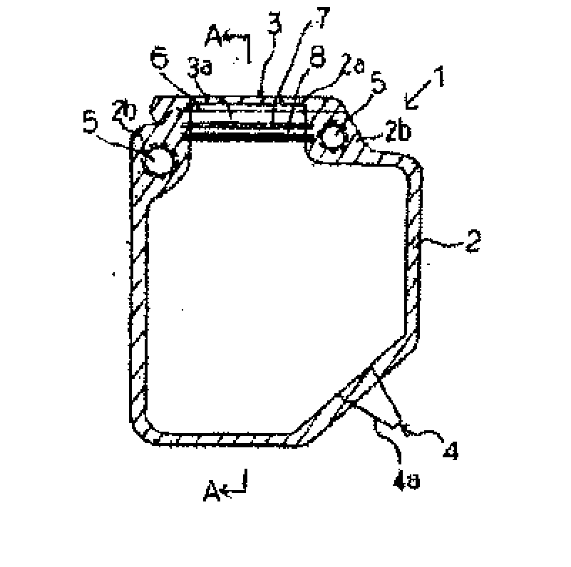
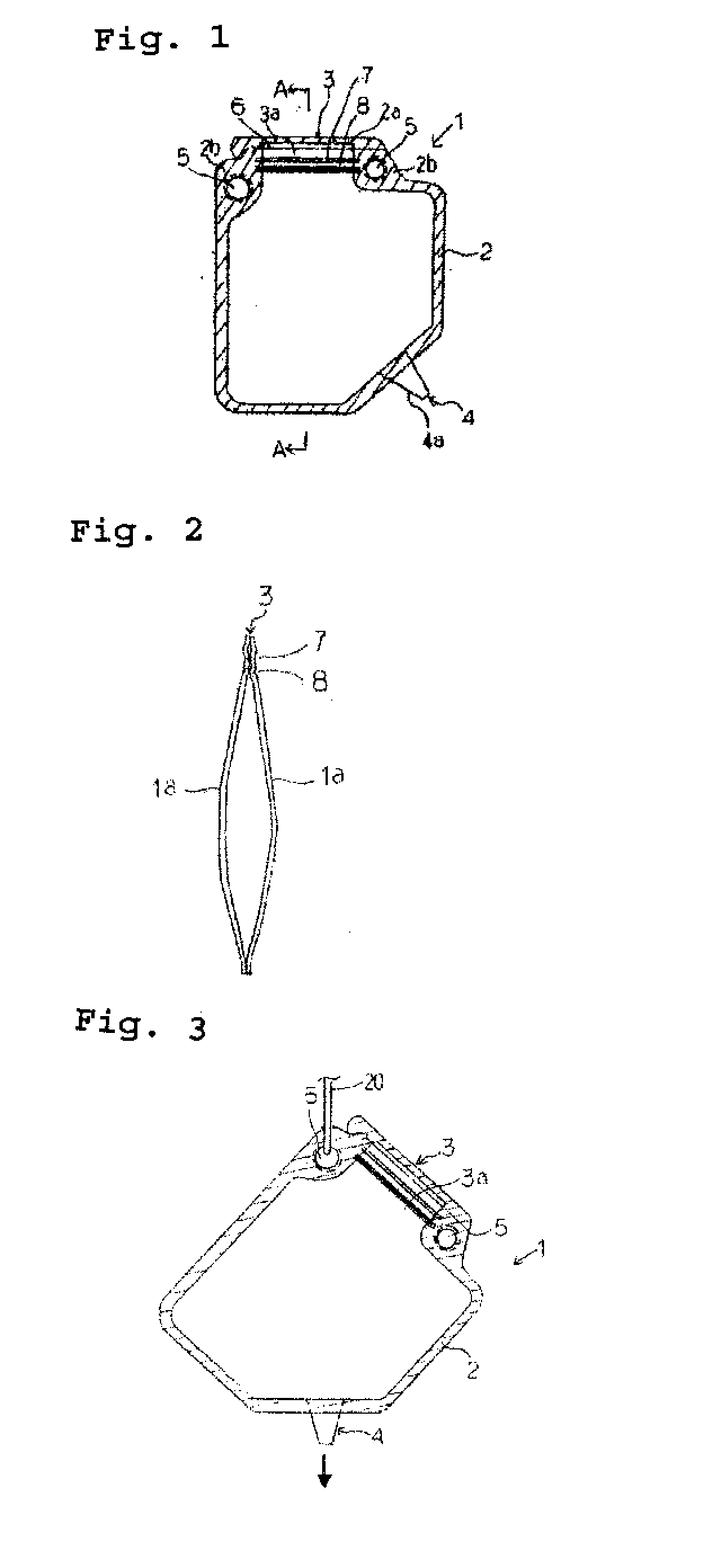
[0074]The present invention is described in more detail below with reference to the drawings. FIG. 1 shows a front view of a packaging bag as an example of an embodiment of the present invention and FIG. 2 shows a sectional view along A-A of the packaging bag of FIG. 1. In FIGS. 1 and 2, a main portion of a packaging bag 1 is formed by sealing peripheral portions 2 of two film pieces 1a, 1a as a sealed portion (shown by hatching in FIG. 1) by fusing or the like. After a peripheral portion of the packaging bag is sealed while leaving a part thereof as an unsealed portion, a contained content is filled into the packaging bag using the unsealed portion as a filling port and then the unsealed portion is sealed. FIG. 14 shows a front view of a packaging bag as an example of an embodiment of the present invention, FIG. 15 shows the construction of the packaging bag of FIG. 14 cut along X-X, and FIG. 16 shows an enlarged view of a part, which becomes an aperture at the time of opening, in ...
second embodiment
[0090]The packaging bag of the present invention is not limited to the above embodiment, and the following arrangement of the inlet portion and the spout portion may be, for example, cited as the one that enables the contained content to be discharged when the packaging bag is suspended. FIG. 9 shows a front view of a packaging bag as another example of the embodiment of the present invention. In FIG. 9, a main portion of a packaging bag 21 is formed by sealing peripheral portions 22 of two film pieces as a sealed portion (shown by hatching in FIG. 9) by fusing or the like. An inlet portion 23 and a spout portion 24 are provided at the peripheral portion 22 of the packaging bag 21. The inlet portion 23 is provided at one corner of an upper side portion 22a of the peripheral portion 22 and an unsealed portion, which becomes an inlet port, projects at a corner portion of the packaging bag. Two holes 25, 25 penetrating through the film pieces are formed at the sealed portion at the opp...
third embodiment
[0091]FIG. 10 shows a front view of a packaging bag as another example of the embodiment of the present invention. In FIG. 10, a main portion of a packaging bag 31 is formed by sealing peripheral portions 32 of two film pieces as a sealed portion (shown by hatching in FIG. 10) by fusing or the like. An inlet portion 33 and a spout portion 34 are provided at the peripheral portion 32 of the packaging bag 31. The inlet portion 33 is constructed similarly to the inlet portion 3 of the packaging bag 1 of FIG. 1 and provided at an upper side portion 32a of the peripheral portion 32. Two holes 35, 35 penetrating through the film pieces are formed at the sealed portion at the opposite sides of an unsealed portion which becomes an unsealed portion, and serve as a suspension means at the time of discharge and a finger holding means when the packaging bag is handled. The spout portion 34 is provided at a bottom piece portion facing the inlet port.
PUM
| Property | Measurement | Unit |
|---|---|---|
| Thickness | aaaaa | aaaaa |
| Thickness | aaaaa | aaaaa |
| Diameter | aaaaa | aaaaa |
Abstract
Description
Claims
Application Information