Conveying device and printing apparatus using same

a conveying device and printing technology, applied in the direction of rotary conveyors, thin material handling, roller-ways, etc., can solve the problems of increasing the conveying distance of print medium, increasing the size of the conveying device, so as to achieve high-quality printing

Active Publication Date: 2011-12-01
COPYER
View PDF9 Cites 31 Cited by
  • Summary
  • Abstract
  • Description
  • Claims
  • Application Information

AI Technical Summary

Benefits of technology

[0015]The present invention has been accomplished to solve the aforementioned problem and provide a conveying device and a printing apparatus using it both of which are capable of high quality printing.

Problems solved by technology

If the front end detection sensor is installed remote from the print head, the back-feed distance becomes long, raising a possibility of jamming.
Further, locating the front end detection sensor remote from the print head also can increase the print medium conveying distance and therefore the size of the conveying device.
Where the transmission type sensor installed near the print head is used to detect the front end of the print medium after the print medium is transported on, and attracted by suction to, the endless conveying belt formed with suction holes, the following problem arises.
However, the portions of the print medium which are not in contact with the conveying belt may curl or deform due to moisture and the printing operation of the print medium.
This in turn gives rise to a problem of degraded print quality and possible damages to the print head.
That is, the sensor detection area of the print medium must not be in contact with the conveying belt, which means that the aforementioned problem can also arise with the reflection type sensor.
In such a case, the aforementioned problem may also occur in other than the areas where the print medium is not in contact with the conveying belt.

Method used


Image

  • Conveying device and printing apparatus using same
  • Conveying device and printing apparatus using same
  • Conveying device and printing apparatus using same

Examples


first embodiment

[0035]Now the first embodiment of this invention will be described by referring to the accompanying drawings.

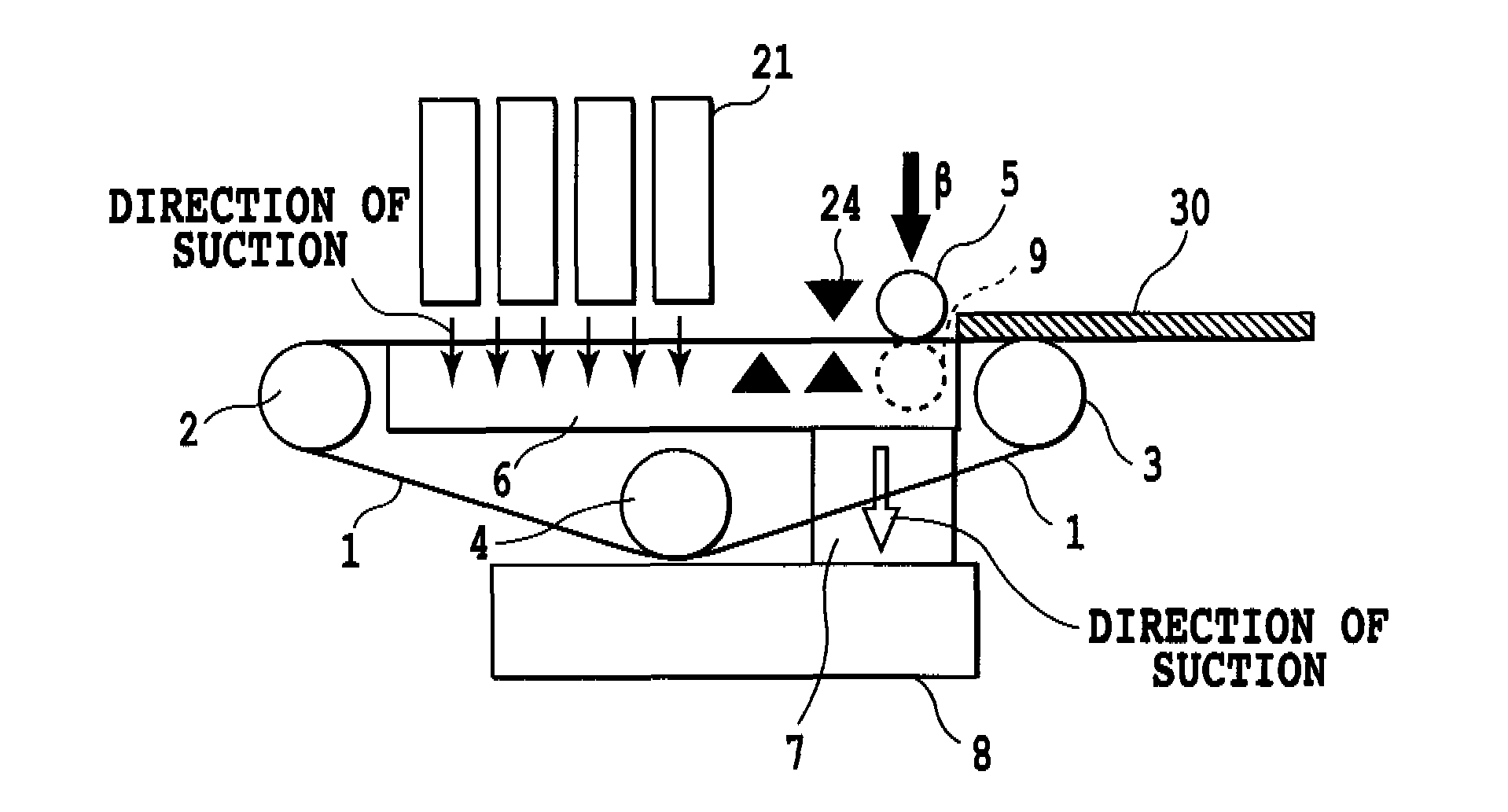
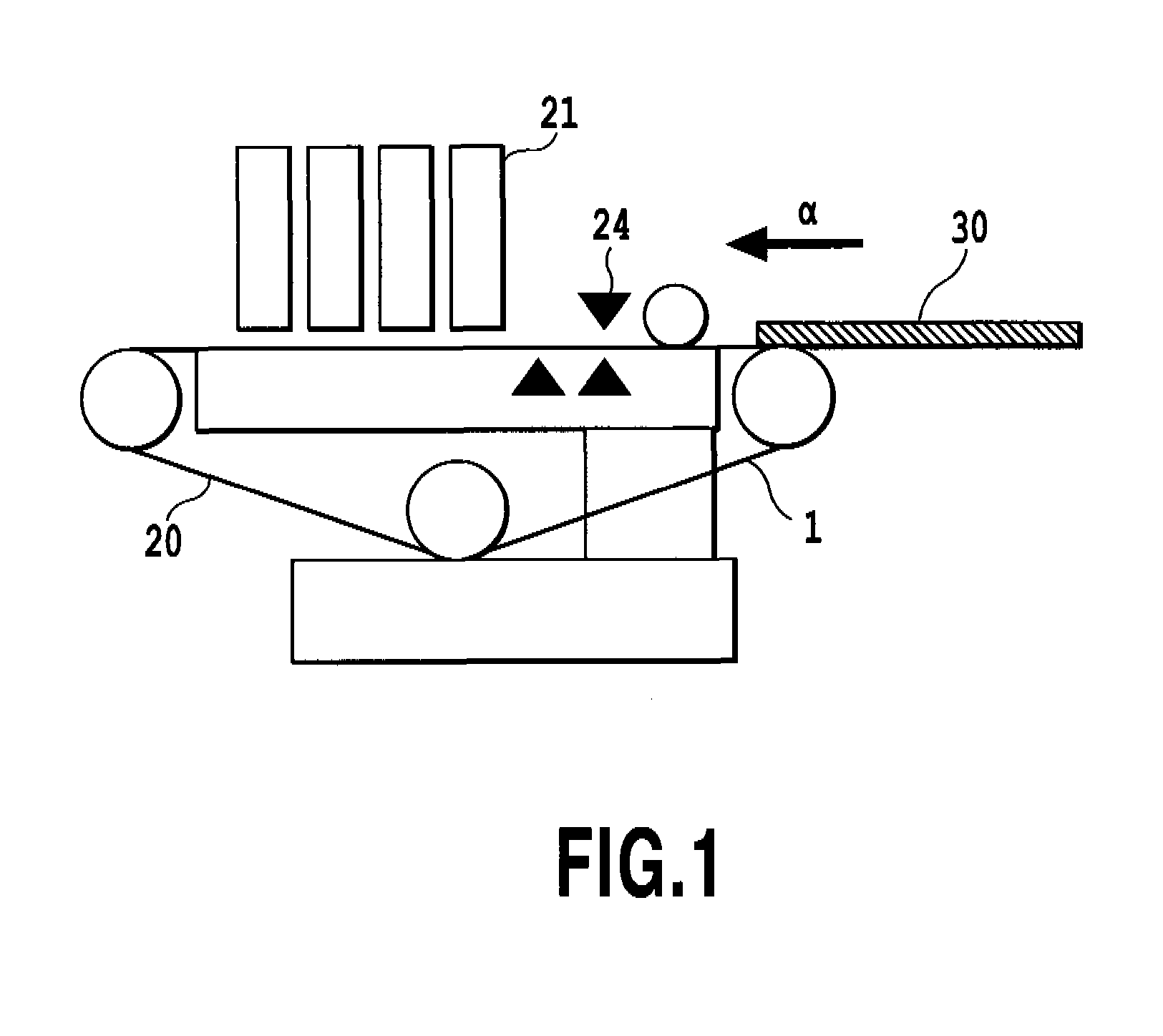
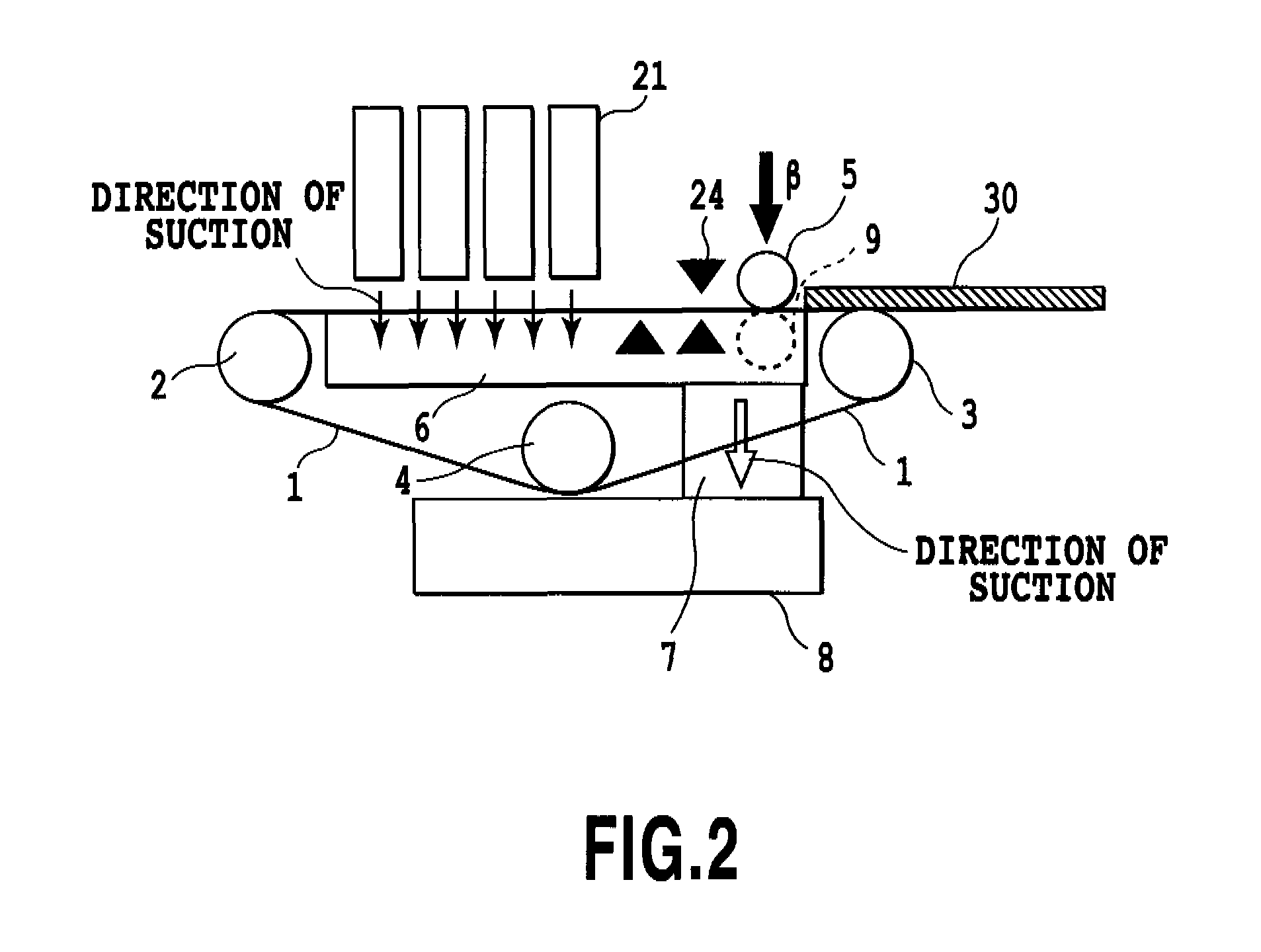
[0036]FIG. 1 is a side view of a conveying unit 20 installed in a printing apparatus, one embodiment of this invention. The printing apparatus of this embodiment has a conveying unit 20 with a conveying belt 1 that holds a print medium 30 to it by suction while transporting the print medium, a print head 21 to print on the print medium 30 by ejecting ink onto the print medium as it is conveyed in a direction of arrow a (the direction of a in this embodiment is taken as a direction of conveyance), and a paper feed unit to feed the print medium 30 onto the conveying belt 1.

[0037]The print head 21 used here is a line head constructed to be of essentially the same length as a maximum print width of the print medium as measured in a direction crossing the conveyance direction and to have a plurality of nozzles arrayed in line. The print head is not limited to this type but may be ...

second embodiment

[0053]The second embodiment differs from the first embodiment in that suction holes 14 are formed in the platen 6. In other respects, it is identical with the first embodiment and detailed explanations are omitted.

[0054]FIG. 12 is a perspective view of the conveying unit in the second embodiment of this invention. FIG. 13 shows details of the portion XIII in FIG. 12. The platen 6 is formed with the suction holes 14 that extend through the bottom of the groove portions 15 in a direction perpendicular to the sliding surface of the conveying belt 1 so as to attract by suction those portions of the print medium 30 which overhang from the conveying belt 1. These suction holes 14 are lined near and along the side edges of the conveying belt 1. The suction holes 14 are provided downstream of the front end detection sensor 24 in the conveyance direction and can attract by suction those portions of the print medium 30 that are outside the conveying belt 1. In this embodiment, there are three...


PUM


Abstract

The conveying device has contact portions that extend in a conveyance direction of the conveying belt and which contact with the same surface of the print medium that is attracted by suction to the conveying belt. This realizes a conveying device that assures a high quality printing. Even when a print medium with warped or undulated portions is fed, the conveying device can hold the print medium flat on the conveying belt and the ribs by suction through the suction holes in the conveying belt and through the platen, keeping the distance between the print head and the print medium constant, assuring a stable printing operation.

Description

BACKGROUND OF THE INVENTION[0001]1. Field of the Invention[0002]The present invention relates to a conveying device that has a conveying means to transport a print medium on a conveying belt by holding it to the belt by suction, and to a printing apparatus using the conveying device.[0003]2. Description of the Related Art[0004]A conveying device that has been proposed in conventional printing apparatus to keep a surface of a print medium from coming into contact with a print head uses a suction device that attracts the print medium to an endless conveying belt by suction.[0005]FIG. 7 is a perspective view of a conveying device disclosed in Japanese Patent Laid-Open No. 2007-302406. An endless conveying belt 41 has a plurality of suction holes piercing therethrough in a direction of the belt thickness and is wound around a drive roller 43 and a follower roller 44, arranged parallel to each other at the same height. On an inner circumferential side of the conveying belt 41 there is pr...

Claims


Application Information

Patent Timeline
Patent Type & Authority Applications(United States)
IPC IPC(8): B41J13/00B65G17/46
CPCB41J11/0085B41J13/08B65G21/2036B65H2801/15B65H5/38B65H2404/513B65H2404/61B65H5/224
Inventor SATO, TAKEHIRO
Owner COPYER
Why Eureka
Try Eureka