Managing autonomous machines across multiple areas

a technology for managing autonomous machines and worksites, applied in the direction of electric programme control, program control, instruments, etc., can solve the problems of physical perimeters, inconvenient operation, and inefficient systems, and achieve the effect of equipment, and reducing the number of peopl

Active Publication Date: 2011-12-01
DEERE & CO
View PDF16 Cites 102 Cited by
  • Summary
  • Abstract
  • Description
  • Claims
  • Application Information

AI Technical Summary

Benefits of technology

[0006]The different illustrative embodiments provide a system for autonomous machine management comprising a number of autonomous machines, a number of nodes, a performance estimation module, and a navigation system. The number of autonomous machines is configured to perform area coverage tasks in a worksite. The number of nodes is configured to define a number of worksite areas for the worksite. The performance estimation module is executed by a processor unit and configured to calculate a percentage of work completed in the number of worksite areas. The navigation system is configured to operate an autonomous machine to perform the area coverage tasks and move between the number of worksite areas.

Problems solved by technology

These systems tend to be inefficient and are often cost-prohibitive.
However, physical perimeters present a challenge in some situations.

Method used


Image

  • Managing autonomous machines across multiple areas
  • Managing autonomous machines across multiple areas
  • Managing autonomous machines across multiple areas

Examples


Embodiment Construction

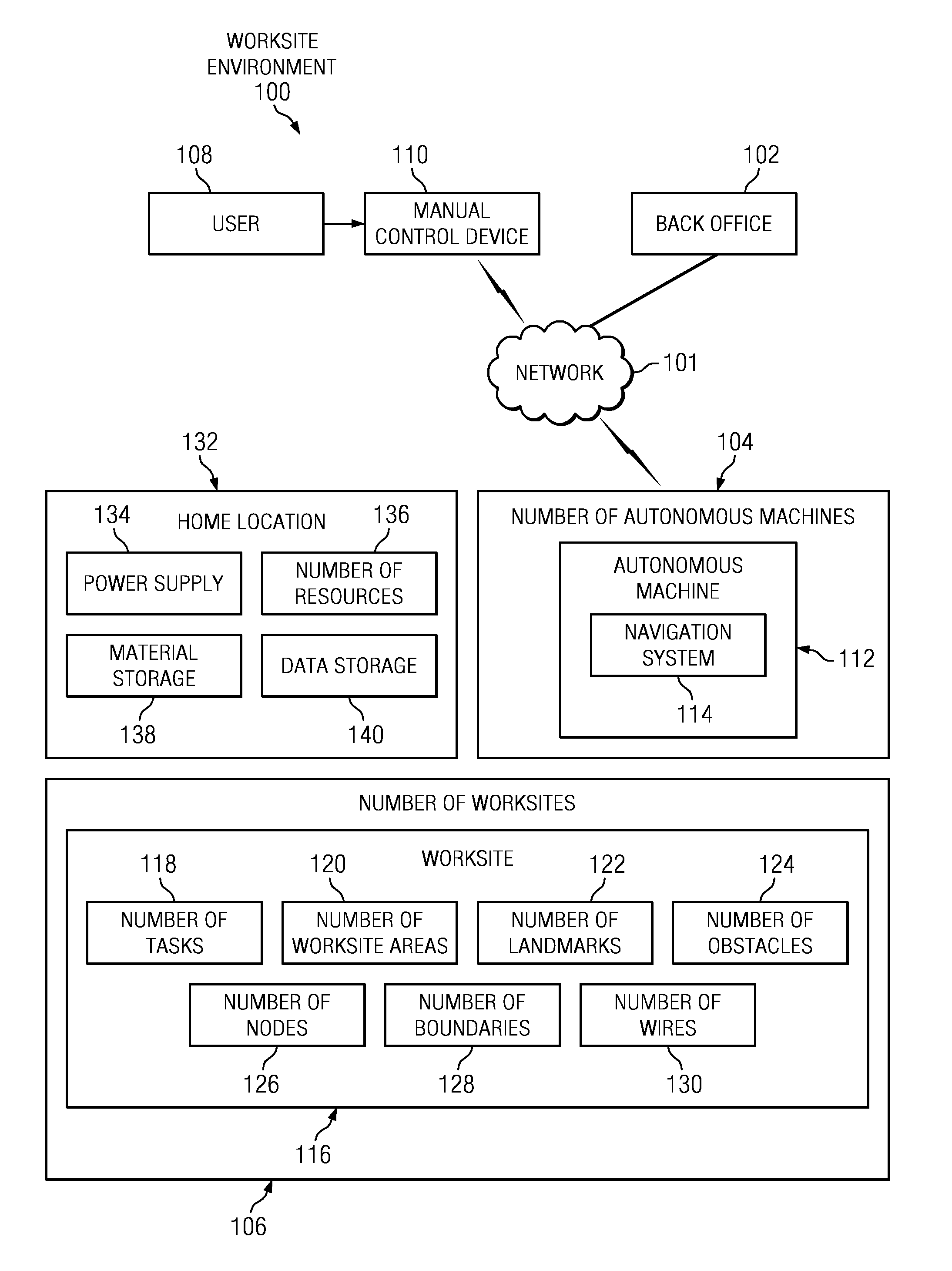
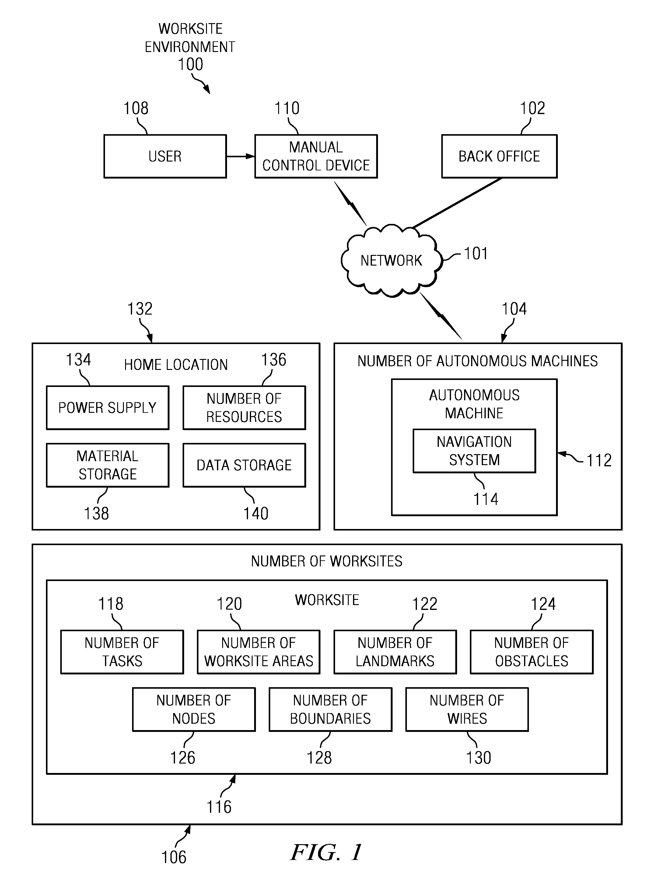
[0022]With reference to the figures and in particular with reference to FIG. 1, a block diagram of a worksite environment is depicted in which an illustrative embodiment may be implemented. Worksite environment 100 may be any type of worksite environment in which an autonomous machine can operate. In an illustrative example, worksite environment 100 may be a structure, building, worksite, area, yard, golf course, indoor environment, outdoor environment, and / or any other suitable worksite environment or combination of worksite environments.

[0023]Worksite environment 100 includes network 101 in one embodiment of the present invention. In this example, back office 102 may be a single computer or a distributed computing cloud. Back office 102 supports the physical databases and / or connections to external databases which may be used in the different illustrative embodiments. Back office 102 may supply databases to different machines, as well as provide online access to information from d...


PUM


Abstract

The different illustrative embodiments provide a system for autonomous machine management comprising a number of autonomous machines, a number of nodes, a performance estimation module, and a navigation system. The number of autonomous machines is configured to perform area coverage tasks in a worksite. The number of nodes is configured to define a number of worksite areas for the worksite. The performance estimation module is executed by a processor unit and configured to calculate a percentage of work completed in the number of worksite areas. The navigation system is configured to operate an autonomous machine to perform the area coverage tasks and move between the number of worksite areas.

Description

CROSS REFERENCE TO RELATED APPLICATIONS[0001]This application is related to commonly assigned and co-pending U.S. patent application Ser. No. ______ (Attorney Docket No. 19129-US) entitled “Condition Based Keep-Out for Machines” all of which are hereby incorporated by reference.FIELD OF THE INVENTION[0002]The present invention relates generally to systems and methods for navigation and more particularly to systems and methods for mobile robotic navigation. Still more specifically, the present disclosure relates to a method and system for managing autonomous machines across multiple worksite areas.BACKGROUND OF THE INVENTION[0003]The use of robotic devices to perform physical tasks has increased in recent years. Mobile robotic devices can be used to perform a variety of different tasks. These mobile devices may operate in semi-autonomous or fully autonomous modes. Some robotic devices are constrained to operate in a contained area, using different methods to obtain coverage within th...

Claims


Application Information

Patent Timeline
Patent Type & Authority Applications(United States)
IPC IPC(8): G05B19/418G01C21/00
CPCA01D34/008G05D1/0219G05D1/0238G05D1/0261G05D2201/0208G05D1/0272G05D1/0274G05D1/0278G05D1/0265
Inventor JOHNSON, DAVID AUGUSTANDERSON, NOEL WAYNEEISENBEIS, KIRK NARUM
Owner DEERE & CO
Why Eureka
Try Eureka