Multiple punch unit for punch presses

a multi-unit, punching machine technology, applied in the field of punching machine, can solve the problems of insufficient reliability and accuracy, no thoroughly effective method, undesired damage to the workpiece, etc., and achieve the effect of preventing undesired conta

Inactive Publication Date: 2011-12-08
EUROMAC SPA
View PDF4 Cites 12 Cited by
  • Summary
  • Abstract
  • Description
  • Claims
  • Application Information

AI Technical Summary

Benefits of technology

[0024]In the light of these and other drawbacks of the prior art, one object of the present invention is to provide a

Problems solved by technology

An undesired damage to the work-piece may be caused by the weight or inertia of one or more of the inactive punches and may be aggravated by the impact force distributed throughout the unit by the fracture caused in the material sheet during punching.
Nevertheless, no thoroughly effective method has been found.
The prior art solutions s

Method used


Image

  • Multiple punch unit for punch presses
  • Multiple punch unit for punch presses
  • Multiple punch unit for punch presses

Examples


Embodiment Construction

[0038]Multiple punch units are known per se, as shown in the above patents.

[0039]While the invention finds application in multiple punch units in general, such as those listed herein, it will be exemplarily described in the multiple punch units as shown in the figures, i.e. FIGS. 1 to 8.

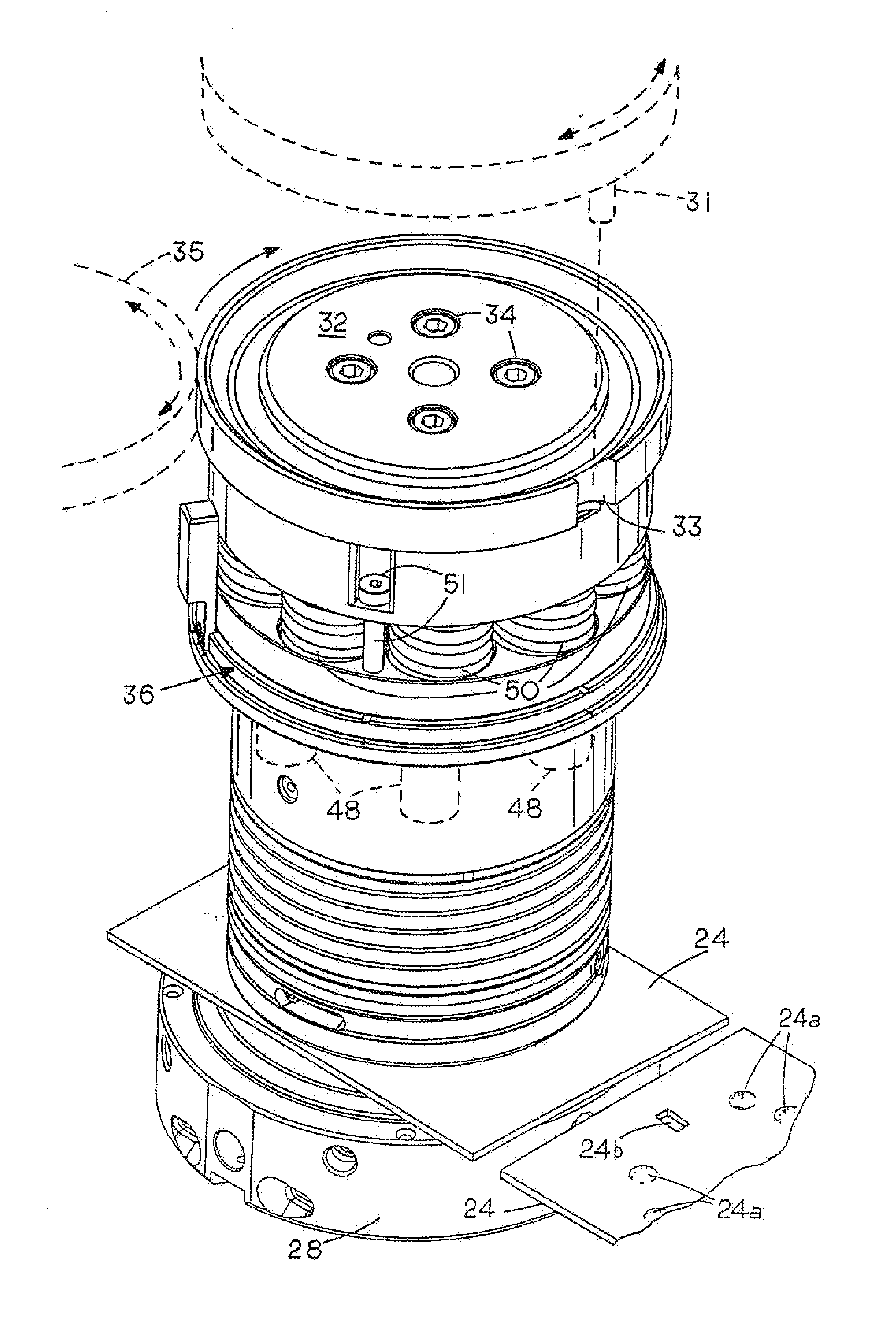
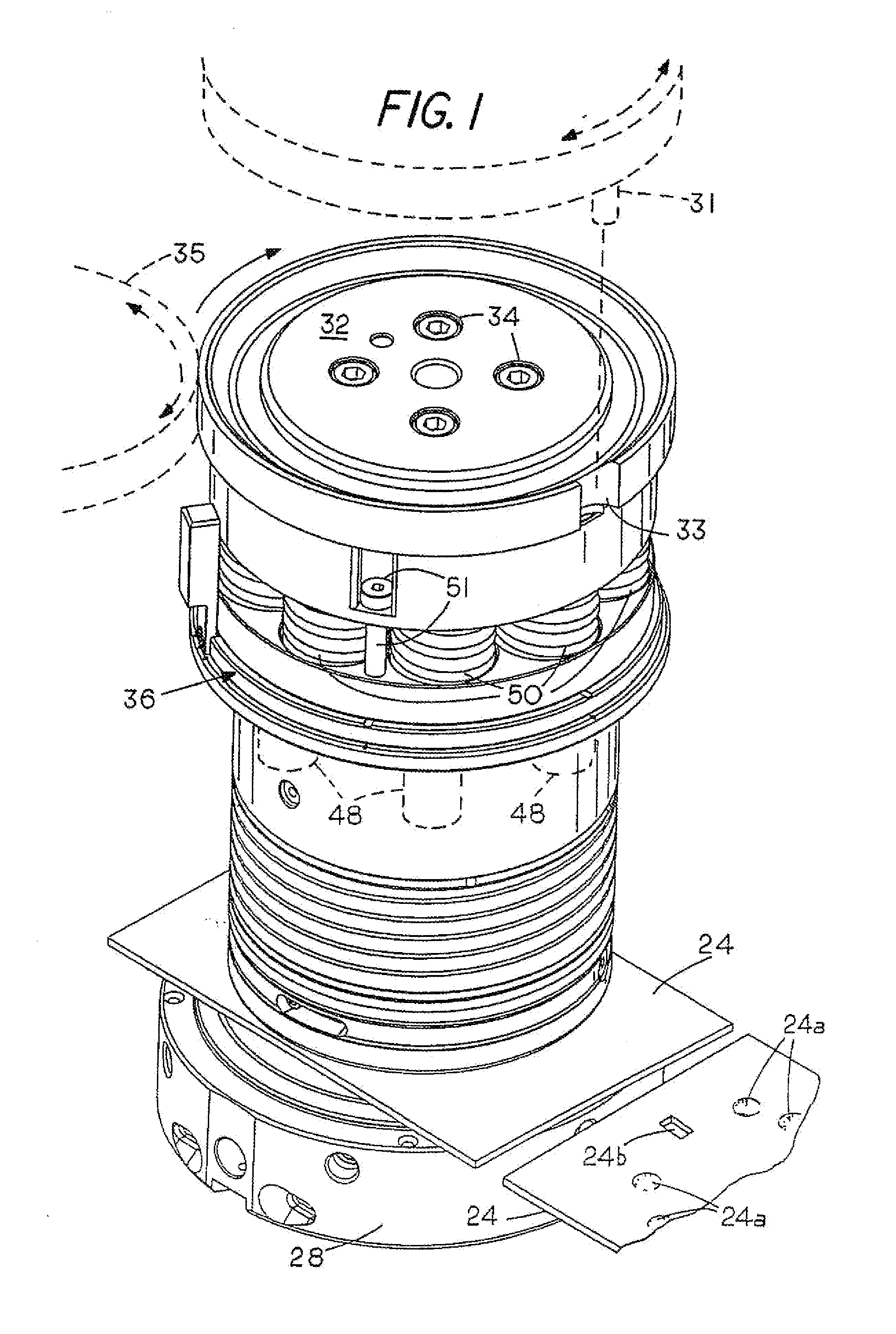
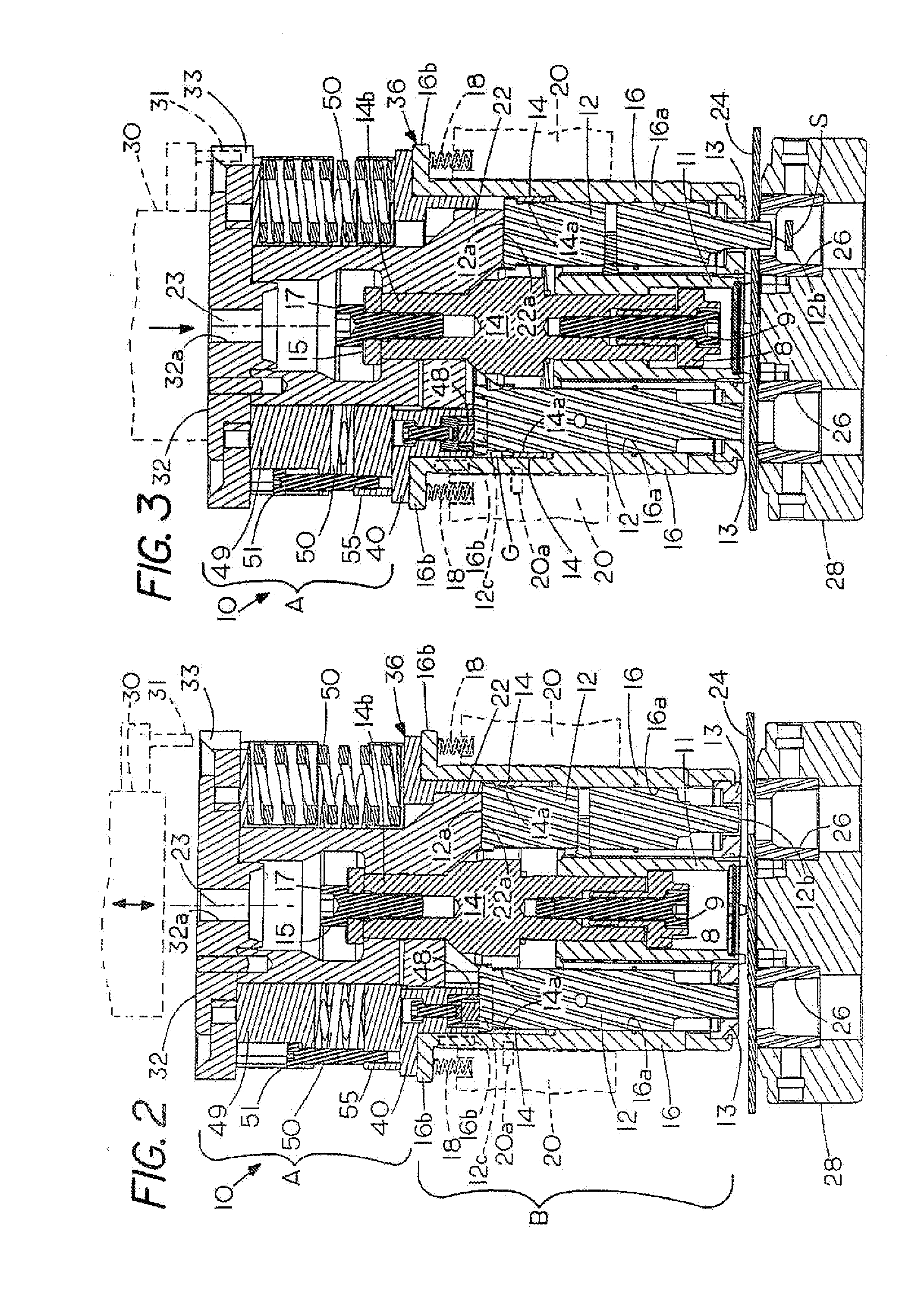
[0040]FIGS. 1 to 3 show a multiple punch apparatus 10 having six punches 12 mounted in circular arrangement to slide along a vertical center axis 23 in apertures formed in circular arrangement into a punch carrier 14, which is in turn slidably mounted to axially move within a vertical hole 16a of a tubular guide seat 16.

[0041]A striking head 12c, whose diameter is larger than that of its shaft, is provided at the upper end of each punch 12, and rests on the punch carrier 14, except during the punching steps, when the punch carrier 14 is raised with the punch striker 22, thereby leaving a gap “G”.

[0042]Therefore, the punch carrier 14 raises the punches 12 by engaging the head 12c with a sufficient for...


PUM

PropertyMeasurementUnit
Permeabilityaaaaaaaaaa
Magnetismaaaaaaaaaa

Abstract

A multiple punch apparatus for punch presses having a provision for preventing undesired damage to a work-piece includes a housing having a plurality of separate punches that include at least one inactive punch and one active punch, each inactive punch being supported in an elevated position by retention magnet means having flux lines oriented to extend into at least each inactive punch when the active punch is in a position in which it is driven into engagement with a work-piece, whereby each inactive punch is magnetically supported to prevent any unintended contact with the work-piece.

Description

FIELD OF THE INVENTION[0001]The invention relates to the field of punches and dies, and more particularly to a multiple punch and multiple die apparatus suitable for use in a punch press for punching or forming sheet materials.BACKGROUND ART[0002]Multiple punch apparatus of the type that is used in automatic, computer-driven high-speed punching presses, are disclosed in U.S. Pat. Nos. 7,032,812; 6,675,688; 6,279,445; 6,074,330; 5,848,563; 5,062,337; 5,048,385; 3,527,130; as well as Ser. No. 11 / 583,530, filed on 19 Oct. 2006.[0003]In a multiple punch apparatus of this type, a common stripping spring or spring assembly is typically provided, which acts upon a single punch carrier that supports and raises all the punches together.[0004]In operation, the hammer strikes on a selected punch (referred to as active punch) to guide it through a work-piece, such as a section of a metal sheet.[0005]Then, the punch is pulled out of the material sheet, whereupon the other inactive pinches are ra...

Claims


Application Information

Patent Timeline
IPC IPC(8): B26D7/26B26F1/04B26D5/08
CPCB21D28/125B21D28/246Y10T83/8748Y10T83/8727Y10T83/9459Y10T83/8867
Inventor LENZOTTI, EUGENIO
Owner EUROMAC SPA
Why Eureka
Try Eureka