Fluid pressure regulating device and fuel supply system using same

a technology of fluid pressure regulating device and fuel supply system, which is applied in the direction of liquid fuel feeder, functional valve type, machine/engine, etc., can solve the problems of difficult installation of device, difficult to compact device, and extremely complex passage configuration, etc., and achieve low cost, easy production, and low cost

Inactive Publication Date: 2011-12-08
TOYOTA JIDOSHA KK +1
View PDF7 Cites 15 Cited by
  • Summary
  • Abstract
  • Description
  • Claims
  • Application Information

AI Technical Summary

Benefits of technology

[0012]The invention thus provides a low cost fluid pressure regulating device that is suitable for switching a set pressure, and in which a passage configuration is able to be simplified, thus enabling the fluid pressure regulating device to be compact, as well as a low cost fuel supply system that uses this fluid pressure regulating device, and is compact due to a simple passage configuration.
[0014]According to this structure, the pressure regulating member that constantly receives urging force in the valve closing direction from an urging mechanism changes the communication state between the fluid introduction side fluid passage and the fluid discharge side fluid passage according to the fluid pressure applied in the valve opening direction inside the pressure regulating chamber. As a result, the pressure of the fuel introduced into the fluid introduction side fluid passage is regulated to a preset set pressure. Further, the other fluid passage can be used for the introduction and / or discharge of fluid, so the set pressure can be switched between the high pressure side and the low pressure side by changing the pressure receiving area of the pressure regulating member, which is accomplished by changing the fluid passage that introduces the fluid, or by changing the fluid pressure inside the other fluid passage in conjunction with the fluid introduction side fluid passage. Moreover, the set pressure can be switched to a plurality of set pressures by controlling the inflow and outflow of fluid with only one side of the pressure regulating member. Therefore, the fluid pressure regulating device is a device that is suitable for switching the set pressure, and in which the passage configuration can be simplified, thus enabling it to be compact and inexpensive. Furthermore, the first valve seat portion and the second valve seat portion are able to be easily produced, while the required seal performance at the one valve seat portion that separates the fluid introduction side fluid passage from the fluid discharge side fluid passage can be stably ensured. Thus, a fuel supply system capable of stably regulating fluid pressure and maintaining that pressure regulating value is able to be provided.
[0016]According to this structure, the set pressure can be switched to one of a plurality of set pressures by controlling the inflow and outflow of fuel with only one side of the pressure regulating member, so a low cost fuel supply system that is suitable for switching the set pressure, and that is compact due to having a simple passage configuration, can be formed. Moreover, the first valve seat portion and the second valve seat portion are able to be easily produced, while the required seal performance at the one valve seat portion that separates the fuel introduction side fluid passage from the fuel discharge side fluid passage is stably ensured. Thus, a fuel supply system capable of stably regulating fluid pressure and maintaining that pressure regulating value is able to be provided.
[0017]According to the fluid pressure regulating device according to the first example embodiment, the pressure receiving area of the pressure regulating member is changed by controlling the inflow and outflow of fluid with only one side of the pressure regulating member. Also, the housing is provided with the first valve seat portion and the second valve seat portion that have different clearances with respect to the pressure regulating member to ensure the sealability at the one valve seat portion that separates the fluid introduction side fluid passage from the fluid discharge side fluid passage. As a result, a low cost fluid pressure regulating device that is capable of stably regulating fluid pressure and maintaining that pressure regulating value, and that is suitable for switching a set pressure, and that is compact due to a simple passage configuration, can be provided.
[0018]The second aspect of the invention makes it possible to provide a low cost fuel supply system that, owing to the fluid pressure regulating device of the invention, enables the fuel pressure to be stably regulated and the regulated pressure value to be maintained, and that is suitable for switching a set pressure, and that is compact due to having a simple passage configuration.

Problems solved by technology

As a result, it is difficult to make the device compact, which in turn makes the device difficult to install.
Also, each of the first to third pressure chambers requires a fluid inlet and a fluid outlet, so the passage configuration becomes extremely complex.
As a result, extra fuel is necessary, and a greater number of portions need to be sealed, which leads to an increase in cost.
Moreover, with a fuel supply system in which an electromagnetic valve is provided in a return line for returning excess fuel that has passed through the fuel gallery from the pressure regulator to the fuel tank, the section of the fuel passage in which the pressure is increased to a high pressure during engine startup becomes wide, and a seal that can withstand the high pressure over that entire area is necessary, which leads to an increase in the cost of the fluid pressure regulating device and the fuel supply system.

Method used


Image

  • Fluid pressure regulating device and fuel supply system using same
  • Fluid pressure regulating device and fuel supply system using same
  • Fluid pressure regulating device and fuel supply system using same

Examples


first example embodiment

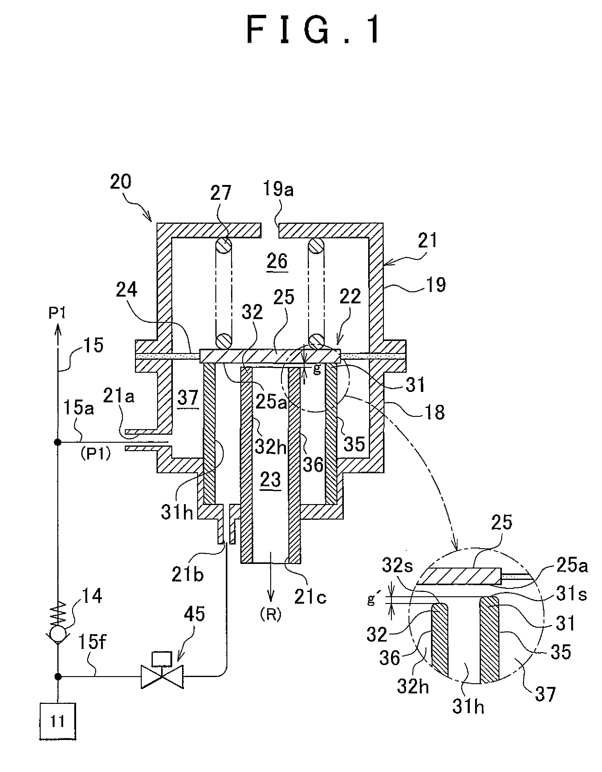
[0039]FIGS. 1 to 4 are views of a fluid pressure regulating device and a fuel supply system that uses this fluid pressure regulating device, according to a first example embodiment of the invention.

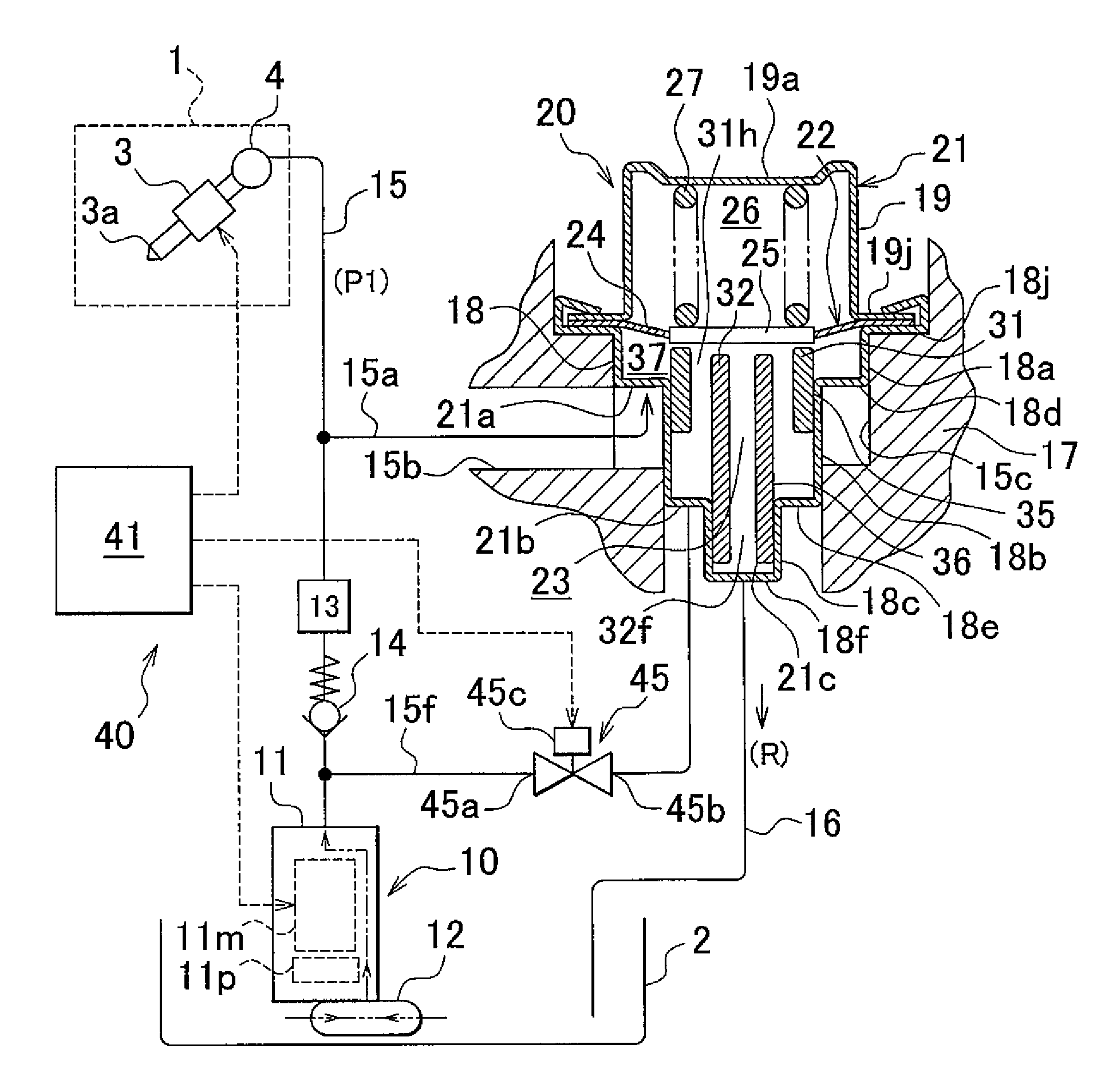
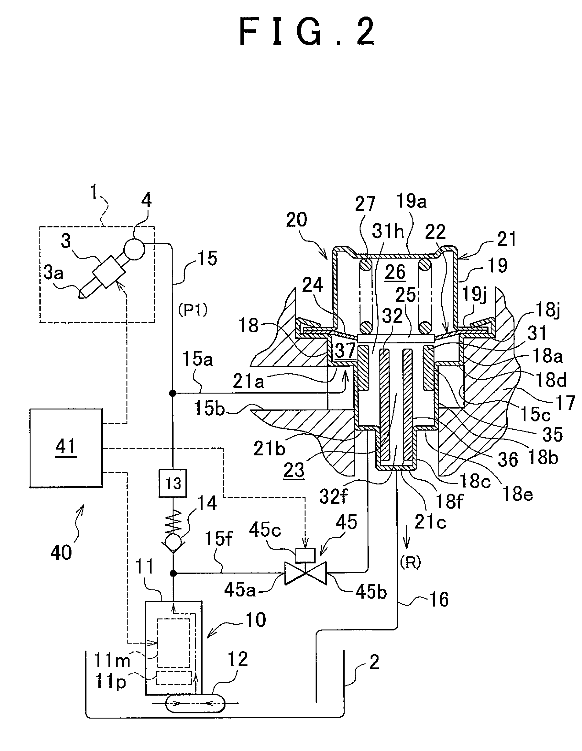
[0040]This example embodiment is an example embodiment in which the invention has been applied to a fluid pressure regulating device that regulates the pressure of fuel in an internal combustion engine for a vehicle, and a fuel supply system that uses this fluid pressure regulating device, and is configured as a so-called in-tank type fuel supply system. That is, although the specific tank structure is not shown, the fuel supply system of this example embodiment includes a pressure regulator housed in a sub tank inside a fuel tank, and delivers fuel of an amount equal to the fuel consumption amount, i.e., the amount of fuel successively consumed by the engine, into the sub tank by a jet pump, for example.

[0041]First, the structure of this example embodiment will be described.

[0042]As show...

second example embodiment

[0108]FIGS. 5 and 6 are views of a fluid pressure regulating device and a fuel supply system using this device, according to a second example embodiment of the invention.

[0109]Incidentally, the example embodiments described below have a structure similar to that of the first example embodiment described above. The constituent elements of the fuel supply system other than the pressure regulator are substantially the same as those of the first example embodiment described above, so only the main portions are shown. Constituent elements that are the same as or similar to those in the first example embodiment described above will be denoted by the same reference characters that denote the corresponding constituent elements shown in FIGS. 1 to 4, and descriptions of those constituent elements will not be repeated. That is, only the differences with respect to the first example embodiment described above will be described below.

[0110]As shown in FIG. 5, the fuel supply system of this seco...

third example embodiment

[0125]FIGS. 7 and 8 are views of a fluid pressure regulating device and a fuel supply system using this device, according to a third example embodiment of the invention.

[0126]As shown in FIG. 7, the fuel supply system of this third example embodiment is provided with a pressure regulator 60. This pressure regulator 60 includes a housing 21 that has an outside communication hole 21a into which pressurized fuel from a fuel pump 11 is constantly introduced when the fuel pump 11 is operating, an inside communication hole 21c to which fuel that has been introduced into a pressure regulating chamber 23 is discharged, and a middle communication hole 21b into which pressurized fuel from the fuel pump 11 is selectively introduced as pilot pressure via an electromagnetic valve 45. A pressure regulating chamber 23 is formed by this housing 21 and a partition-shaped pressure regulating member 62, just as in the first example embodiment.

[0127]Also, the pressure regulating member 62 is formed by ...


PUM


Abstract

A fluid pressure regulating device is i) provided with a pressure regulating member that forms a pressure regulating chamber inside a housing having introduction side and discharge side fuel passages, and communicates these passages according to introduced fuel pressure, and ii) is able to regulate the fuel pressure introduced into a fuel passage to a set pressure. The housing is provided with outer and inner annular valve seat portions that separate the fuel passages inside the pressure regulating chamber, and form another fuel passage inside the pressure regulating chamber. Different clearances are set between the pressure regulating member, and the outer annular valve seat portion and the inner annular valve seat portion, such that when the pressure regulating member abuts against one of the valve seat portions, a small gap is formed between the other valve seat portion and the pressure regulating member.

Description

INCORPORATION BY REFERENCE[0001]The disclosure of Japanese Patent Application No. 2010-126966 filed on Jun. 2, 2010 including the specification, drawings and abstract is incorporated herein by reference in its entirety.BACKGROUND OF THE INVENTION[0002]1. Field of the Invention[0003]The invention relates to a fluid pressure regulating device and a fuel supply system that uses this fluid pressure regulating device. More particularly, the invention relates to a fluid pressure regulating device suited to regulating fuel pressure when supplying fuel for an internal combustion engine from a fuel pump to a fuel injection valve.[0004]2. Description of Related Art[0005]A fuel supply system of an internal combustion engine mounted in a vehicle or the like typically supplies fuel from a fuel pump to an injector (i.e., a fuel injection valve), and regulates the fuel pressure inside a fuel supply passage using a pressure regulator, i.e., a fluid pressure regulating device. In this kind of fuel s...

Claims


Application Information

Patent Timeline
Patent Type & Authority Applications(United States)
IPC IPC(8): F02M69/54F16K21/04
CPCF02M37/0029F02D2250/31F02M69/54F02M37/0058F02M37/0052Y10T137/7793Y10T137/7837
Inventor AKAGI, MASAKISUZUKI, HIROMASANISHIBU, HIDEAKIYOSHIDA, KOJIMURAKOSHI, YUICHI
Owner TOYOTA JIDOSHA KK
Why Eureka
Try Eureka