Hinge joint assembly

Inactive Publication Date: 2011-12-08
BASIL BANGS
View PDF27 Cites 29 Cited by
  • Summary
  • Abstract
  • Description
  • Claims
  • Application Information

AI Technical Summary

Benefits of technology

[0038]As will be appreciated, the abovementioned hinge joint assembly provides a quick locking and/or quick release mechanism. The hinge joint a

Problems solved by technology

As will be appreciated, however, if the teeth are too small, this may compromi

Method used


Image

  • Hinge joint assembly
  • Hinge joint assembly
  • Hinge joint assembly

Examples


Example

[0059]A description of the embodiment or embodiments of the present invention, as illustrated in the abovementioned drawings, is provided below.

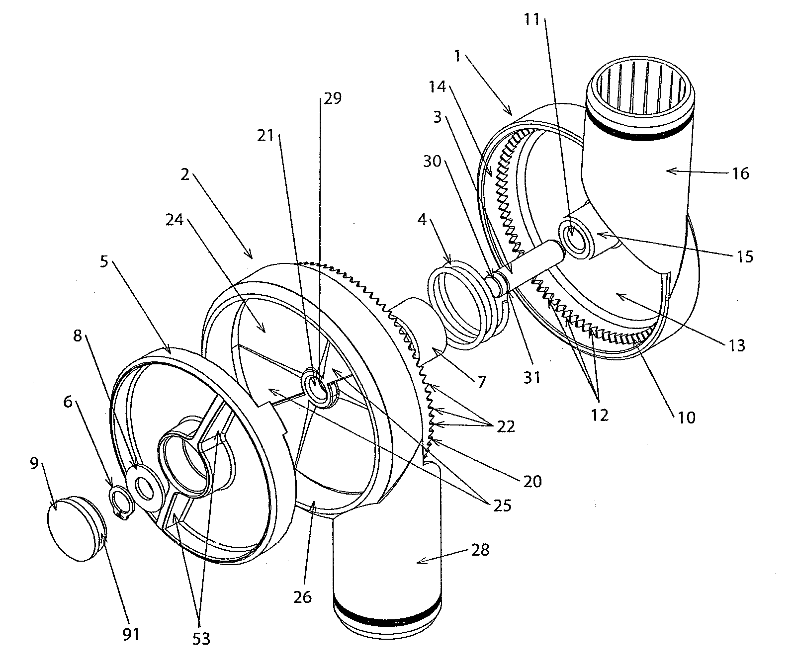
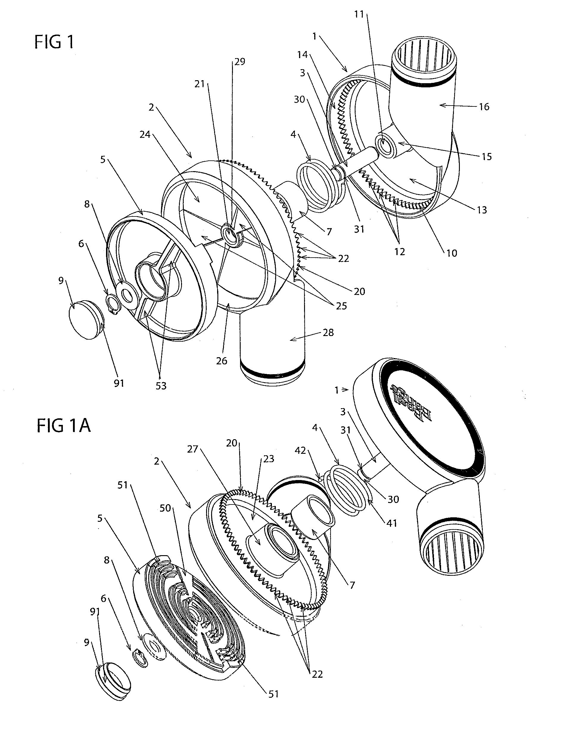
[0060]As can be seen from FIGS. 1, 1A and 3, the hinge joint assembly according to a preferred embodiment of this invention includes a number of components, including a first body 1, a second body 2, an axle rod 3, a coil spring 4, a cam element 5, a circlip 6, a bush piece 7, a washer 8, and a cap 9.

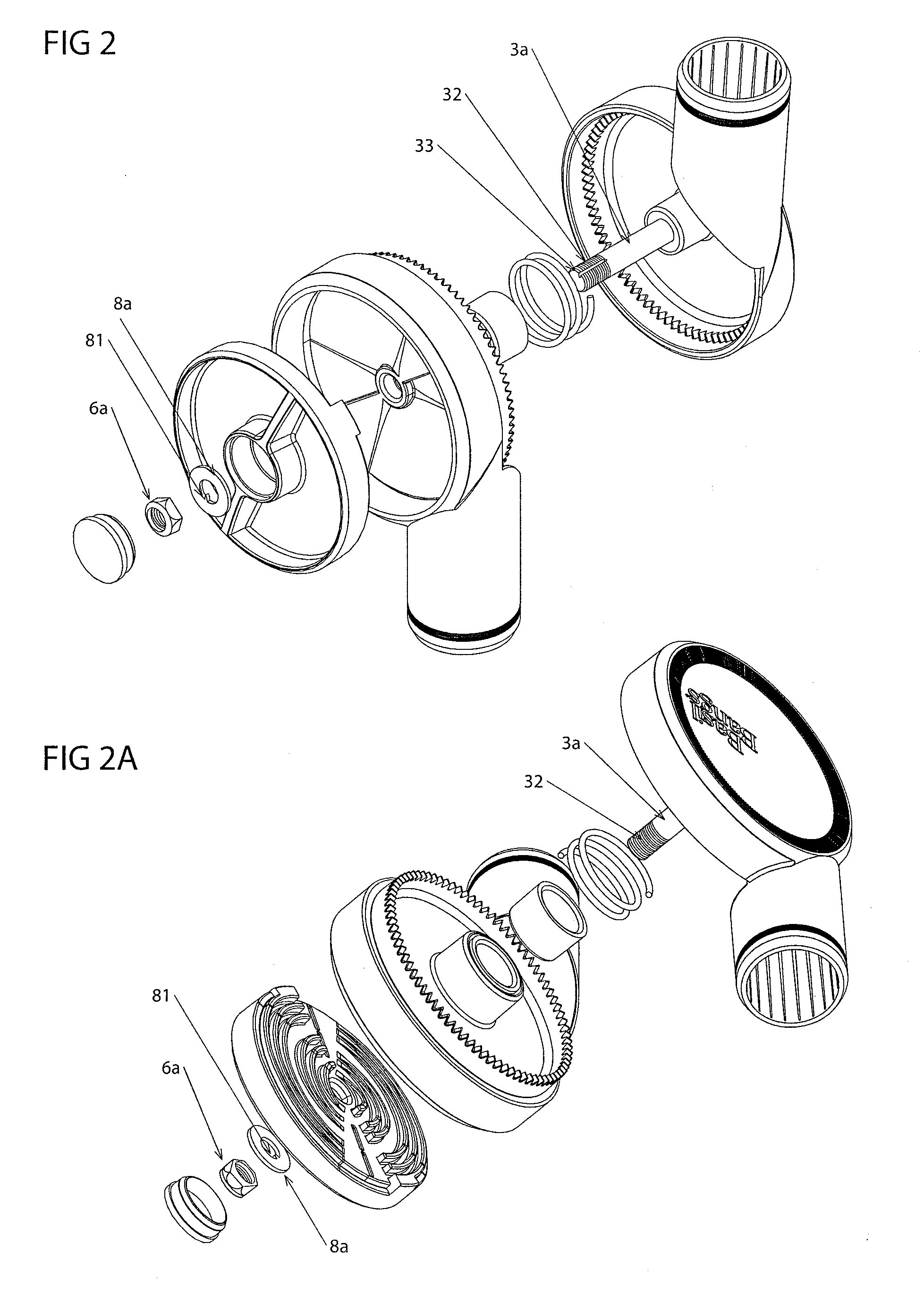
[0061]FIGS. 2 and 2A show an alternative preferred embodiment which is largely the same as the preferred embodiment shown in FIGS. 1 and 1A. The only real differences in the alternative preferred embodiment of FIGS. 2 and 2A are the following:[0062]the circlip 6 (of FIGS. 1 and 1A) has been replaced by a lock nut 6a; [0063]the washer 8 (of FIGS. 1 and 1A) has been replaced by a washer 8a which includes a nipple 81 protruding from an inner circumference of the washer 8a; [0064]the axle rod 3a (of FIGS. 2 and 2A) is molded into first body 1;[0065]...


PUM


Abstract

A hinge joint assembly including a first body having a first circular serrated edge located around a first central axis; a second body having a second circular serrated edge located around a second central axis, said second circular serrated edge corresponding with and adapted to engage with the first circular serrated edge; an axle rod, extending through the first central axis and the second central axis, adapted to enable the first and second bodies to rotate relative to one another; biasing means, positioned between the first body and the second body, for biasing said first and second bodies away from each other along the axle rod; movement limiting means for preventing the second body from being separated from the first body beyond a pre-determined distance; and a cam element, rotatable about the axle rod, adapted to move the second body relative to the first body, from a joint locked position to a joint unlocked position.

Description

[0001]The present application claims priority under 35 U.S.C §. 119 to Australian provisional patent application no. 2010902434 which was filed on 3 Jun. 2010, which is hereby incorporated by reference in its entirety.FIELD OF THE INVENTION[0002]The present invention relates to hinge joints adapted to be rotated and to be, selectively, locked into one of two or more desired orientations. The present invention has particular application in relation to articles such as outdoor umbrellas, lamp stands, computer monitor extension arms and similar items for which it is often desirable to have two or more arms or legs rotatable relative to one another and lockable in a number of different orientations.BACKGROUND OF THE INVENTION[0003]Numerous different types of hinge joints are known and a number of these do have the ability to enable the joints to be rotated and locked into a number of selected orientations. Such hinge joints find use in numerous applications, including outdoor umbrellas,...

Claims


Application Information

Patent Timeline
IPC IPC(8): A45B25/02E05F1/12E05D11/10
CPCA45B17/00A45B2023/0012Y10T16/5385Y10T16/54E05D11/1007
Inventor DURANTE, MICHAEL
Owner BASIL BANGS
Why Eureka
Try Eureka