
Method and Apparatus for Attaching a Personal Electronic Device

a technology for electronic devices and personal devices, applied in the direction of machine supports, building scaffolds, other domestic objects, etc., can solve the problems of user's hands and arms becoming tired, screens that may be difficult to view under direct light or sunligh

Inactive Publication Date: 2011-12-08
YU DAVID CHEN +1
View PDF12 Cites 15 Cited by
  • Summary
  • Abstract
  • Description
  • Claims
  • Application Information

AI Technical Summary

Benefits of technology

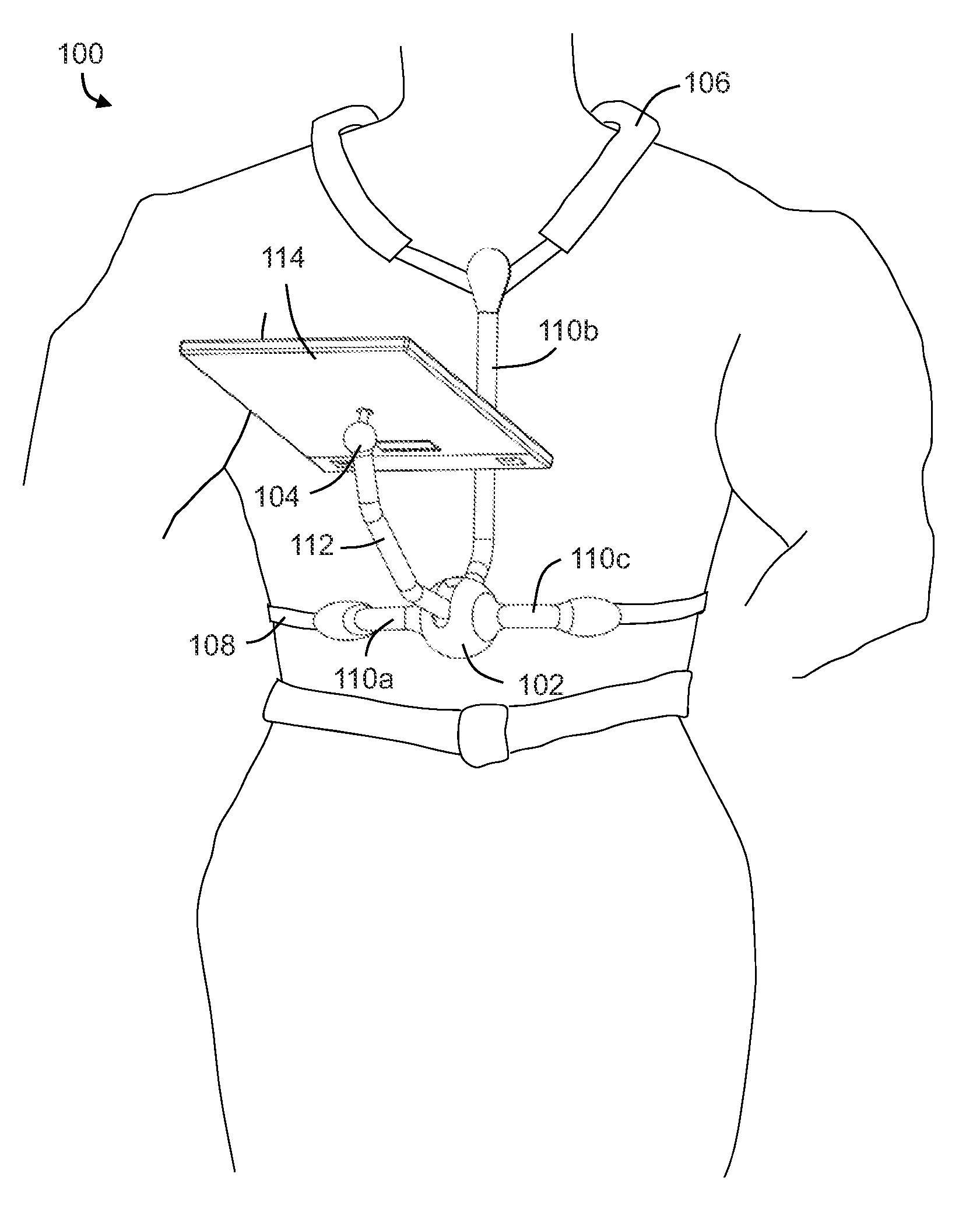
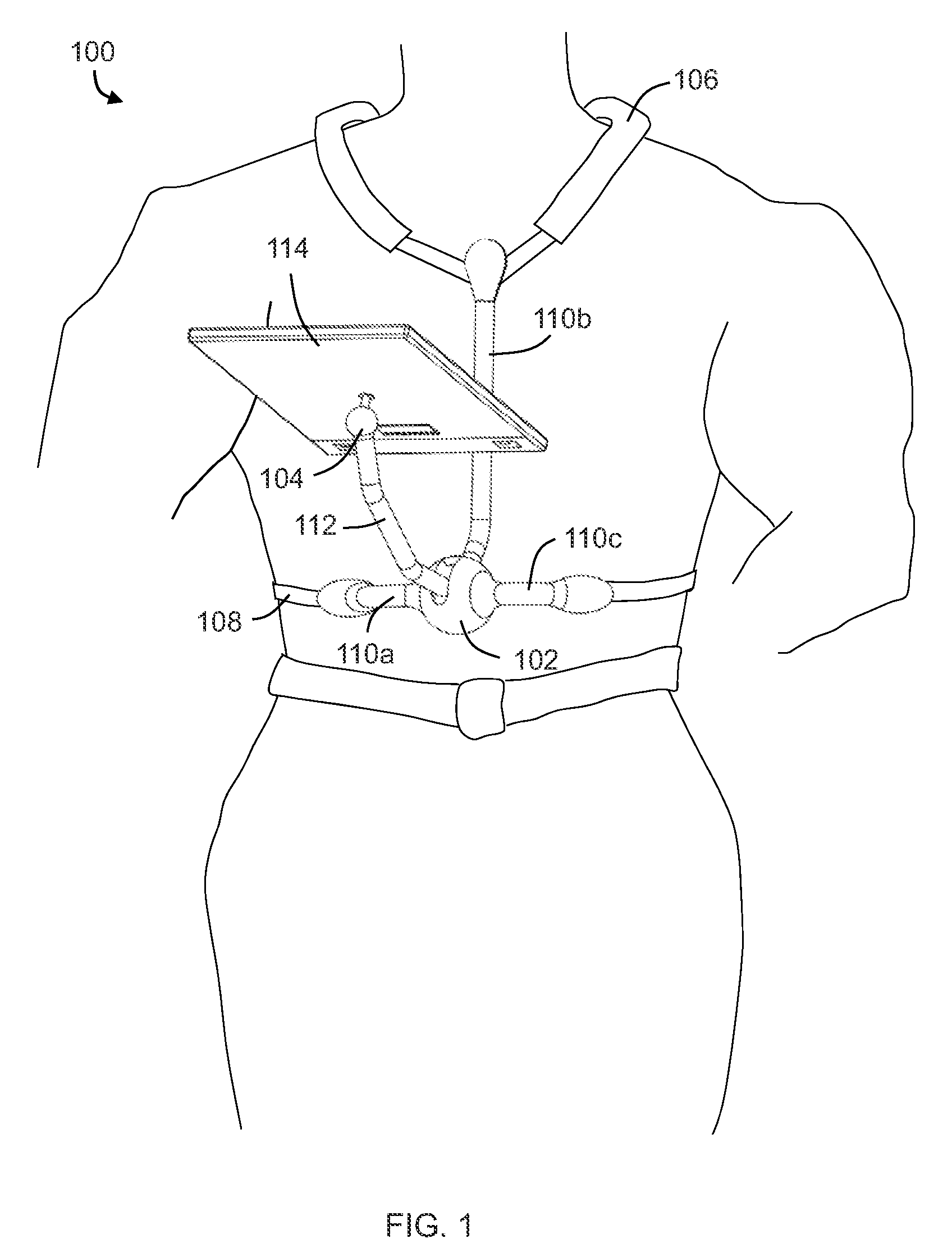
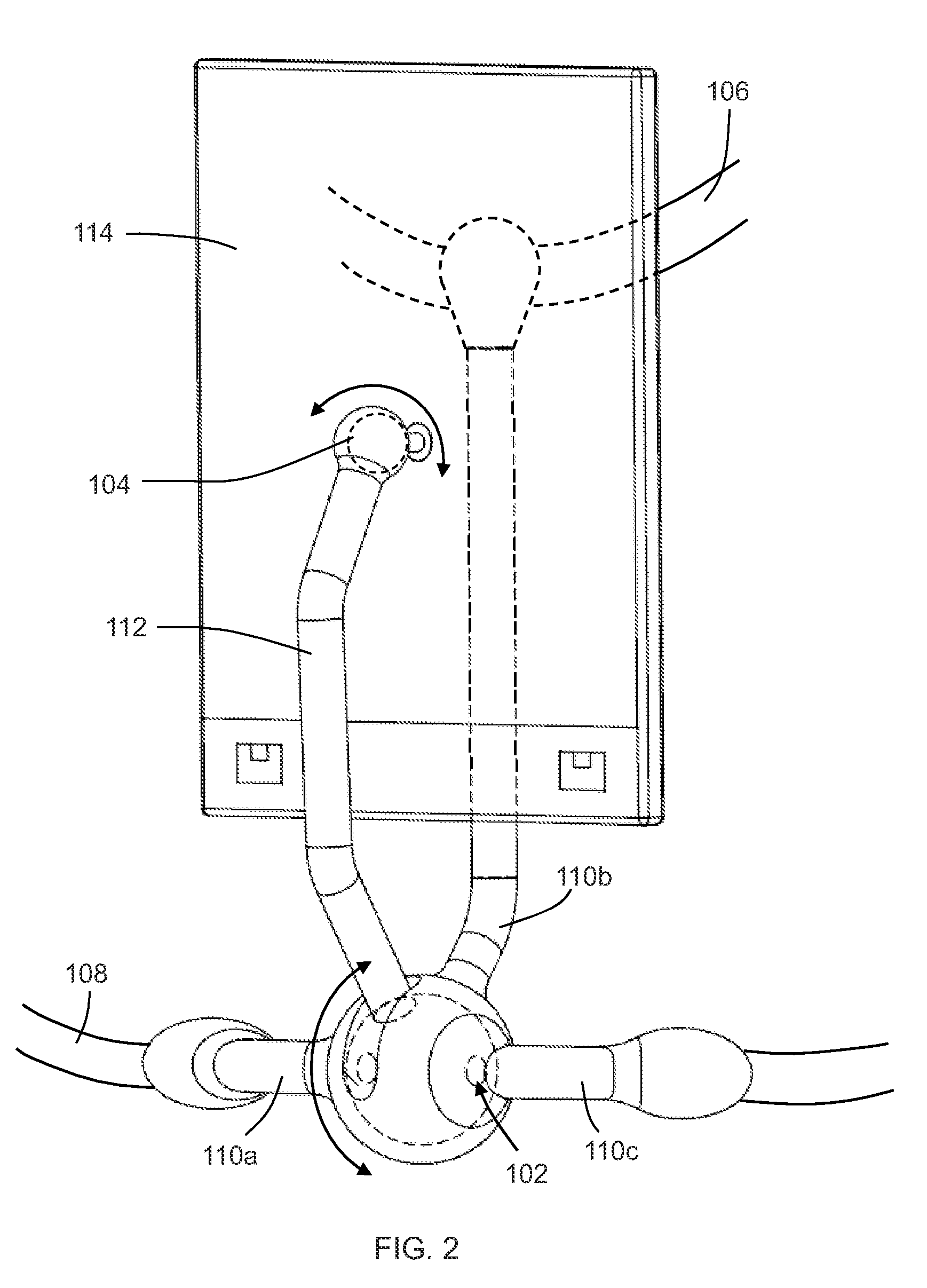
"The patent describes an apparatus for supporting an electronic device, which allows the user to adjust the viewing angle of the screen. The attachment system includes a shoulder strap and a chest strap, which attach to a support frame. The lower joint of the support frame allows for the user to adjust the viewing angle of the screen. The electronic device attaches to an electronic device support leg that is attached to the lower joint. The end opposite the lower joint incorporates a ball joint, which allows for rotating the screen. The technical effect of this invention is to provide a convenient and flexible way to support and adjust the viewing angle of electronic devices."

Problems solved by technology

In addition, the larger size of these devices may cause a user's hands and arms to become tired when holding the device for a long period of time, such as when viewing a movie.
Smaller than a laptop, tablet-style devices feature screens that may be difficult to view under direct light or sunlight.

Method used


Image

  • Method and Apparatus for Attaching a Personal Electronic Device
  • Method and Apparatus for Attaching a Personal Electronic Device
  • Method and Apparatus for Attaching a Personal Electronic Device

Examples


Embodiment Construction

[0014]Various embodiments are now described with reference to the drawings, wherein like reference numerals are used to refer to like elements throughout. In the following description, for purposes of explanation, numerous specific details are set forth in order to provide a thorough understanding of one or more embodiments. It may be evident, however, that such embodiment(s) may be practiced without these specific details. In other instances, well-known structures and devices are shown in block diagram form in order to facilitate describing one or more embodiments.

[0015]In the following paragraphs, the present invention will be described in detail by way of example with reference to the attached drawings. Throughout this description, the preferred embodiment and examples shown should be considered as exemplars, rather than as limitations on the present invention. As used herein, the “present invention” refers to any one of the embodiments of the invention described herein, and any ...


PUM


Abstract

A method and apparatus for supporting a personal electronic device are provided. The device incorporates a support frame structure comprised of three legs. A vertical leg is attached to a shoulder strap, while the horizontal legs are attached to a chest strap. A lower joint is located between the two horizontal legs and this lower joint is also attached to an electronic device support leg. The electronic device support leg is attached to the lower joint and also to a ball joint at the end opposite the lower joint. In use, the lower joint allows for the electronic device to be moved into a viewing position at a desired angle. The ball joint allows rotation of the device between portrait and landscape orientations. A case may also be attached to the electronic device support leg to contain the personal electronic device.

Description

BACKGROUND OF THE INVENTION[0001]The present invention pertains to a method and apparatus for attaching a personal electronic device.[0002]Personal electronic devices have become extremely popular, providing on-the-go entertainment and data access. While many devices are hand-held size, the popularity of these devices has led to the introduction of larger tablet-style devices with larger screens. These larger devices may also allow a user to access the Internet using a keyboard appearing on the screen.[0003]Tablet-style personal electronic devices may require a user to use both hands, particularly when trying to enter data on the on-screen keyboard. Because these devices are larger, a user may need to place the device on a table to enter the data. In addition, the larger size of these devices may cause a user's hands and arms to become tired when holding the device for a long period of time, such as when viewing a movie.[0004]One reason for the great popularity of tablet-style perso...

Claims


Application Information

Patent Timeline
Patent Type & Authority Applications(United States)
IPC IPC(8): A45F3/00B65D85/00F16M13/00
CPCA45F3/10A45F5/00F16M11/14F16M2200/027F16M13/04F16M2200/022F16M11/24
Inventor YU, DAVID C.YU, MICHAEL D.
Owner YU DAVID CHEN
Learn More