
Novel holographic electronic aiming device

A collimator and holographic technology, which is applied in the field of electronic collimators, can solve problems such as unclear holographic images, poor laser coherence, and output wavelength changes, and achieve the effects of adjustable magnification and viewing angle, improved stability, and rapid heat dissipation

Inactive Publication Date: 2016-09-21
GUIZHOU JINGHAO TECH
View PDF7 Cites 4 Cited by
  • Summary
  • Abstract
  • Description
  • Claims
  • Application Information

AI Technical Summary

Problems solved by technology

[0004] In the prior art, although it has been proposed that the holographic sight can be made small and light, it still cannot meet the second requirement above. The reasons are: (1) During the use of the sight, the temperature of the LD increases and the output wavelength (2) The coherence of the laser emitted by the LD is poor, which makes the aberration of the hologram very large, so the holographic image is not clear

Method used


Image

  • Novel holographic electronic aiming device
  • Novel holographic electronic aiming device
  • Novel holographic electronic aiming device

Examples


Embodiment Construction

[0020] In order to make the object, technical solution and advantages of the present invention clearer, the present invention will be further described in detail below in conjunction with the accompanying drawings and embodiments. It should be understood that the specific embodiments described here are only used to explain the present invention, not to limit the present invention.

[0021] On the contrary, the invention covers any alternatives, modifications, equivalent methods and schemes within the spirit and scope of the invention as defined by the claims. Further, in order to make the public have a better understanding of the present invention, some specific details are described in detail in the detailed description of the present invention below. The present invention can be fully understood by those skilled in the art without the description of these detailed parts.

[0022] The present invention provides a novel holographic electronic sight, comprising a holographic l...


PUM


Abstract

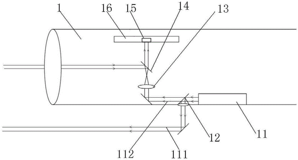
The invention belongs to the technical field of electronic aiming devices, and particularly relates to a novel holographic electronic aiming device. The novel holographic electronic aiming device includes a holographic lens, an image sensor, a processor and a holographic display screen; the holographic lens, the image sensor, the processor and the holographic display screen are connected successively; the holographic lens is fixed on a gun; the holographic lens is internally provided with a holographic image capturing unit which can freely move in the horizontal direction; and the holographic image capturing unit is connected to the image sensor. According to the novel holographic electronic aiming device, the holographic lens is arranged on the gun, and when the holographic image capturing unit in the lens acquires a holographic image, multiplying power of the lens is adjusted, and then the image acquired by the holographic image capturing unit can change with the changeable view, the size is small, and the multiplying power and the view can be adjusted; and the holographic display screen is arranged at another place and is not integrated into the electronic aiming device, and the stability can be improved in long term use.

Description

technical field [0001] The invention belongs to the technical field of electronic sights, and in particular relates to a novel holographic electronic sight. Background technique [0002] The holographic sight uses the reproduced holographic virtual image to aim, which has the advantages of fast aiming, high aiming accuracy, and is not affected by climate and environmental conditions. Holographic sights can be installed on various firearms. Because they have advantages over other types of sights in close-range gun battles, holographic sights have been highly valued by military departments of various countries in recent years. [0003] A holographic sight must contain a laser diode (LD) and a hologram. The laser emitted by the LD is irradiated on the hologram, and the human eye can see a holographic division image presented in the distance through the hologram, and use this image to aim at the target to be shot. In the development of the holographic sight, there are two poin...

Claims


Application Information

Patent Timeline
Patent Type & Authority Applications(China)
IPC IPC(8): F41G1/46G02B23/00G02B5/32
Inventor 李貌李丹阳龚亚云
Owner GUIZHOU JINGHAO TECH
Learn More