View angle adjustment mechanism in view device

a technology of angle adjustment and view device, which is applied in the direction of optical viewing, vehicle components, transportation and packaging, etc., can solve the problems of not easy to assemble the view element and the view element holder, and achieve the effect of enhancing the stiffness of the view element holder, and reducing the number of components

Active Publication Date: 2017-10-05
MURAKAMI CORP
View PDF3 Cites 4 Cited by
  • Summary
  • Abstract
  • Description
  • Claims
  • Application Information

AI Technical Summary

Benefits of technology

[0006]A view angle adjustment mechanism according to this invention is configured to support a view element tilting section holding a view element by a tilting support section via at least two concentric pivots having different diameters, the pivots including an inner pivot and an outer pivot, so as to be capable of adjusting a view angle of the view element, wherein: the view element tilting section includes a view element holder holding the view element; the inner pivot and the outer pivot are formed between the tilting support section and the view element holder; the view element holder and the tilting support section are joined to each other via the inner pivot; the outer pivot has a structure in which an outer-pivot convex surface formed at the view element holder and an outer-pivot concave surface formed at the tilting support section are slidably fitted together; and the outer-pivot convex surface is formed in an outer circumferential surface of an outer-pivot convex surface-forming annular wall formed at a back surface of the view element holder in an integrated manner. According to this invention, the inner pivot and the outer pivot are formed between the tilting support section and the view element holder, and thus, a plate pivot, which is used in conventional devices, is not required, which reduces the number of components. In addition, the outer-pivot convex surface is formed by the outer-pivot convex surface-forming annular wall formed at the back surface of the view element holder in an integrated manner, and thus, a stiffness of the view element holder can be enhanced by the outer-pivot convex surface-forming annular wall.
[0007]In this invention, it is possible that the inner pivot is assembled by forcible fitting without screw fastening. Where the inner pivot and the outer pivot are formed between the tilting support section and the view element holder, if the inner pivot is of a screw fastening type, the view element cannot be assembled to the view element holder unless the view element holder is assembled to the tilting support section by means of screw fastening. Therefore, it is not easy to assemble the view element to the view element holder. In other words, a screw fastening position is located behind the view element, and thus, if the view element is assembled to the view element holder first, no screw fastening can be performed. Accordingly, it cannot be helped that the view element holder is fastened to the tilting support section via a screw first, but it is not easy to assemble the view element to the view element holder with the view element holder fastened to the tilting support section via a screw. On the other hand, if the inner pivot is of a forcible-fastening type without screw fastening, there is no need to fasten the view element holder to the tilting support section via a screw, and thus, the view element can be assembled to the view element holder before the view element holder is assembled to the tilting support section. Accordingly, assembling the view element to the view element holder becomes easy.
[0008]In this invention, it is possible that a general plate thickness of an area, between the inner pivot and the outer pivot, of a plate of the view element holder is set to be larger than a general plate thickness of an area on an outer circumferential side of the plate of the view element holder relative to the outer pivot. Accordingly, a stiffness of the area, between the inner pivot and the outer pivot, of the view element holder can be enhanced, enabling effective suppression of element vibration. Concurrently, a stiffness of the area on the outer circumferential side of the view element holder relative to the outer pivot is lowered compared to the area between the inner pivot and the outer pivot, enabling easy fitting of the view element to the view element holder. It is possible that: the view element holder includes an outer auxiliary annular wall at the back surface of the view element holder in an integrated manner, the outer auxiliary annular wall being disposed concentrically to the outer-pivot convex surface-forming annular wall with a gap therebetween, on an outer circumferential side of the outer-pivot convex surface-forming annular wall; the tilting support section includes an outer-pivot concave surface-forming annular wall with the outer-pivot concave surface being formed at an inner circumferential surface thereof; and the outer-pivot concave surface-forming annular wall is inserted into the gap between the outer-pivot convex surface-forming annular wall and the outer auxiliary annular wall and moved inside the gap upon tilting of the view element holder relative to the tilting support section. Accordingly, the outer-pivot concave surface-forming annular wall is inserted into the gap between the outer-pivot convex surface-forming annular wall and the outer auxiliary annular wall, and thus, entry of, e.g., foreign substances and / or water into space inside the outer pivot can be suppressed. Also, grease can be held in the gap by charging the grease in the gap. Also, the outer circumferential surface of the outer-pivot convex surface-forming annular wall, to which the grease adheres, is covered by the outer auxiliary annular wall, and thus, at the time of assembling the view element tilting section and the tilting support section, the grease adhering to the outer circumferential surface of the outer-pivot convex surface-forming annular wall can be prevented from adhering to the hands of a worker. Also, the stiffness of the view element holder can further be enhanced by the outer auxiliary annular wall.
[0009]In this invention, it is possible that: the outer-pivot convex surface-forming annular wall includes an annular wall body forming the outer-pivot convex surface and an inner auxiliary annular wall disposed on an inner circumferential side of the annular wall body; a top of the annular wall body and a top of the inner auxiliary annular wall are coupled to each other; and the annular wall body and the inner auxiliary annular wall are disposed concentrically to each other across a space in a radial direction as viewed from a front side of the view element holder. Accordingly, a stiffness of the outer-pivot convex surface-forming annular wall, which is a structure part on the view element holder side of the outer pivot, can be enhanced by a dual structure formed of the annular wall body and the inner auxiliary annular wall. It is possible that: the annular wall body includes a plurality of elastic pieces at a plurality of positions in a circumferential direction of the annular wall body, the plurality of elastic pieces being formed by cutting the annular wall body; and the plurality of elastic pieces slidably and elastically abut on the outer-pivot concave surface formed at the tilting support section. Accordingly, the elastic pieces formed at the outer-pivot convex surface of the view element holder slidably and elastically abut on the outer-pivot concave surface of the tilting support section, enabling suppression of element vibration caused by, e.g., a wind generated by movement of the vehicle or vibration of the vehicle (due to, e.g. road unevenness or engine vibration). Also, as a result of forming the elastic pieces by cutting the annular wall body, holes are formed in the annular wall body, but the disposition of the inner auxiliary annular wall on the inner circumferential side of the annular wall body enables suppression of entry of, e.g., foreign substances and / or water into the space inside the outer pivot. It is possible that the view element holder includes a rib joining the annular wall body and the inner auxiliary annular wall in the space formed between the annular wall body and the inner auxiliary annular wall. Accordingly, the stiffness of the outer-pivot convex surface-forming annular wall having a dual structure formed of the annular wall body and the inner auxiliary annular wall can be enhanced by the rib. In particular, where the elastic pieces are formed by cutting the annular wall body, disposition of the rib at each of positions on opposite sides in a circumferential direction of each elastic piece enables compensation for decrease in stiffness of the annular wall body due to the cutting, and thus enables enhances the effect of the elastic pieces.

Problems solved by technology

Therefore, it is not easy to assemble the view element to the view element holder.
Accordingly, it cannot be helped that the view element holder is fastened to the tilting support section via a screw first, but it is not easy to assemble the view element to the view element holder with the view element holder fastened to the tilting support section via a screw.

Method used


Image

  • View angle adjustment mechanism in view device
  • View angle adjustment mechanism in view device
  • View angle adjustment mechanism in view device

Examples


Embodiment Construction

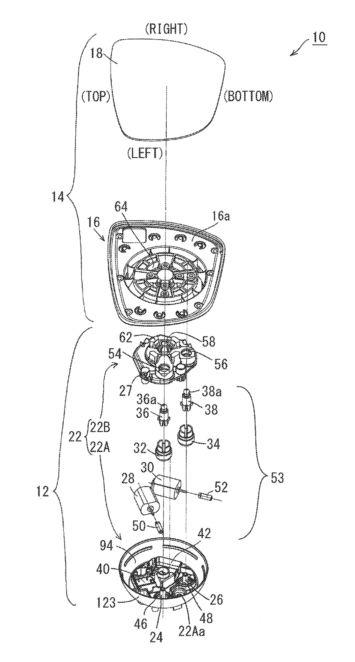
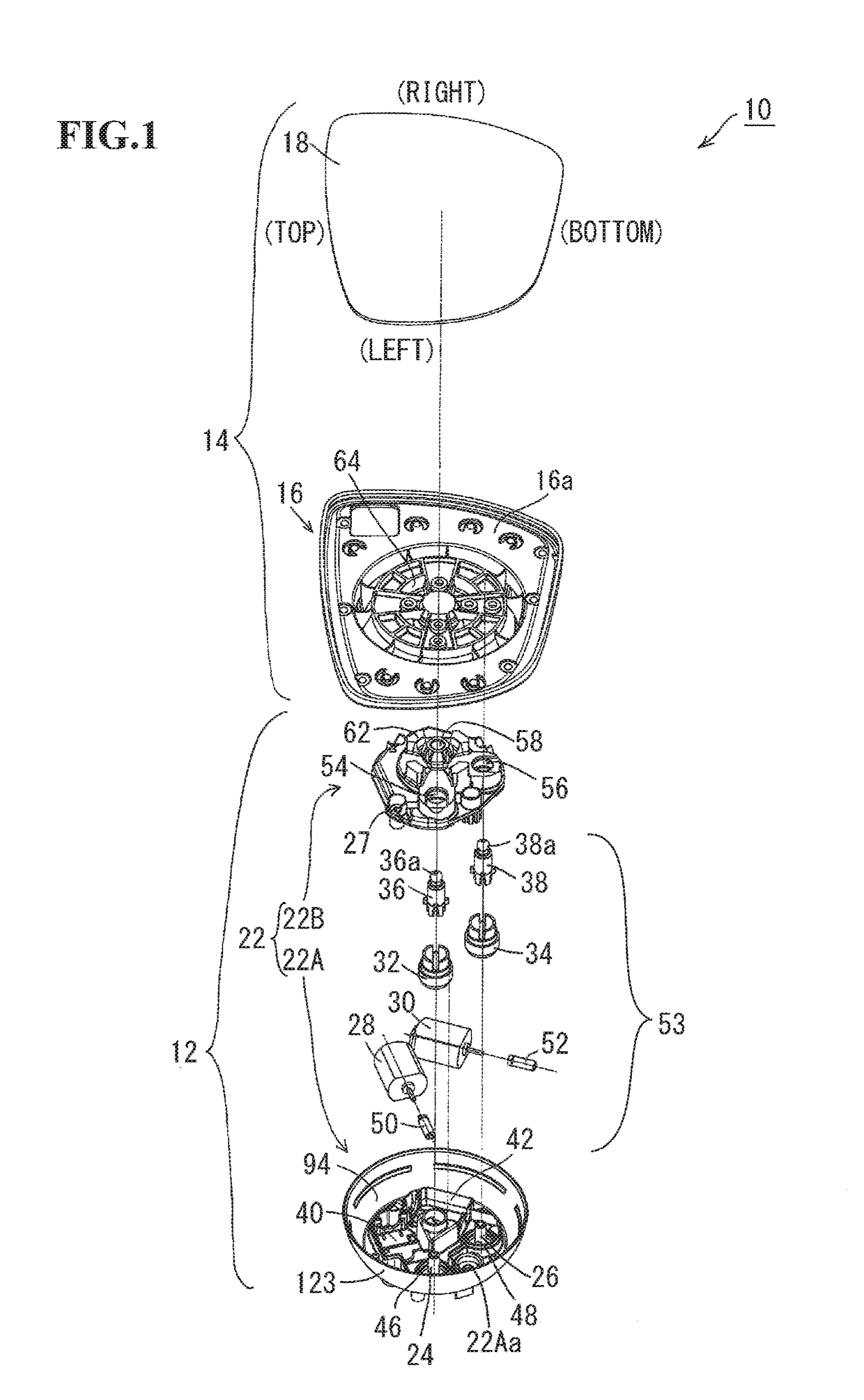
[0041]An embodiment of this invention will be described. FIG. 1 is an exploded perspective view of a tilting device 10 of a left-side door mirror for a vehicle to which this invention is applied. This tilting device 10 has a structure based on tilting devices described in Japanese Patent Laid-Open Nos. 2014-159221 and 2014-159222 relating to patent applications filed by the present applicant. The tilting device 10 includes a tilting support section 12 and a mirror tilting section 14. The tilting support section 12 is attached to the inside of an opening of a non-illustrated mirror housing (visor). The mirror tilting section 14 is formed by fitting a mirror 18 (mirror plate) into a recess 16a in a front surface of the mirror holder 16 formed by integral molding using a synthetic resin. The mirror tilting section 14 is joined and supported by a front surface of the tilting support section 12 via pivots to perform mirror surface angle adjustment by means of electromotive driving. The t...


PUM


Abstract

This invention relates to a view angle adjustment mechanism. A view element tilting section is tiltably supported by a tilting support section via an inner pivot and an outer pivot. The view element tilting section includes a view element holder holding a view element. The inner pivot and the outer pivot are formed between the tilting support section and the view element holder. The outer pivot has a structure in which an outer-pivot convex surface formed at the view element holder and an outer-pivot concave surface formed at the tilting support section are slidably fitted together. The outer-pivot convex surface is formed in an outer circumferential surface of an outer-pivot convex surface-forming annular wall formed at a back surface of the view element holder in an integrated manner.

Description

[0001]The disclosure of Japanese Patent Application No. JP2016-071958 filed on Mar. 31, 2016 including the specification, drawings, claims and abstract is incorporated herein by reference in its entirety.BACKGROUND OF THE INVENTIONField of the Invention[0002]This invention relates to a view angle adjustment mechanism in a view device including a view element such as a mirror or a camera. In this view angle adjustment mechanism, a view element tilting section holding the view element is supported by a tilting support section via a plurality of concentric pivots having different diameters (that is, sharing a common center and having different diameters) to perform angle adjustment (view direction adjustment). The view angle adjustment mechanism of this invention is one with a stiffness of a view element holder holding the view element enhanced while the number of components being reduced.Description of the Related Art[0003]As one kind of view devices, there is a mirror device for a ve...

Claims


Application Information

Patent Timeline
Patent Type & Authority Applications(United States)
IPC IPC(8): B60R1/072
CPCB60R1/072B60R1/06B60R1/02
Inventor SUGIMURA, NAOMI
Owner MURAKAMI CORP
Why Eureka
Try Eureka