Planar illumination device and display device provided with the same
- Summary
- Abstract
- Description
- Claims
- Application Information
AI Technical Summary
Benefits of technology
Problems solved by technology
Method used
Image

Examples
first embodiment
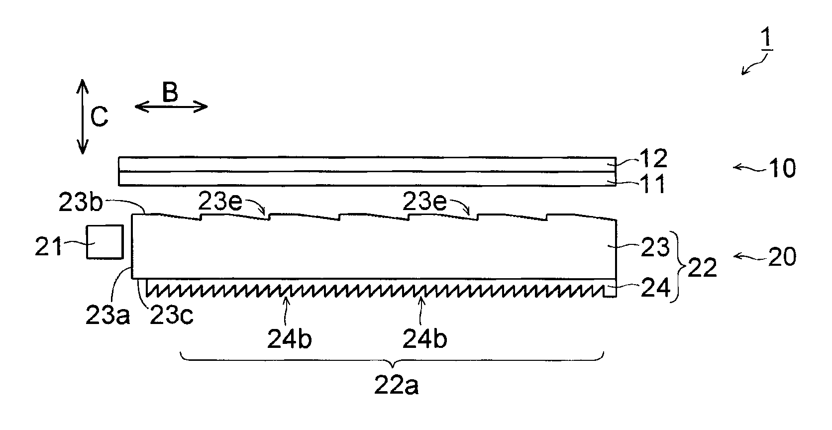
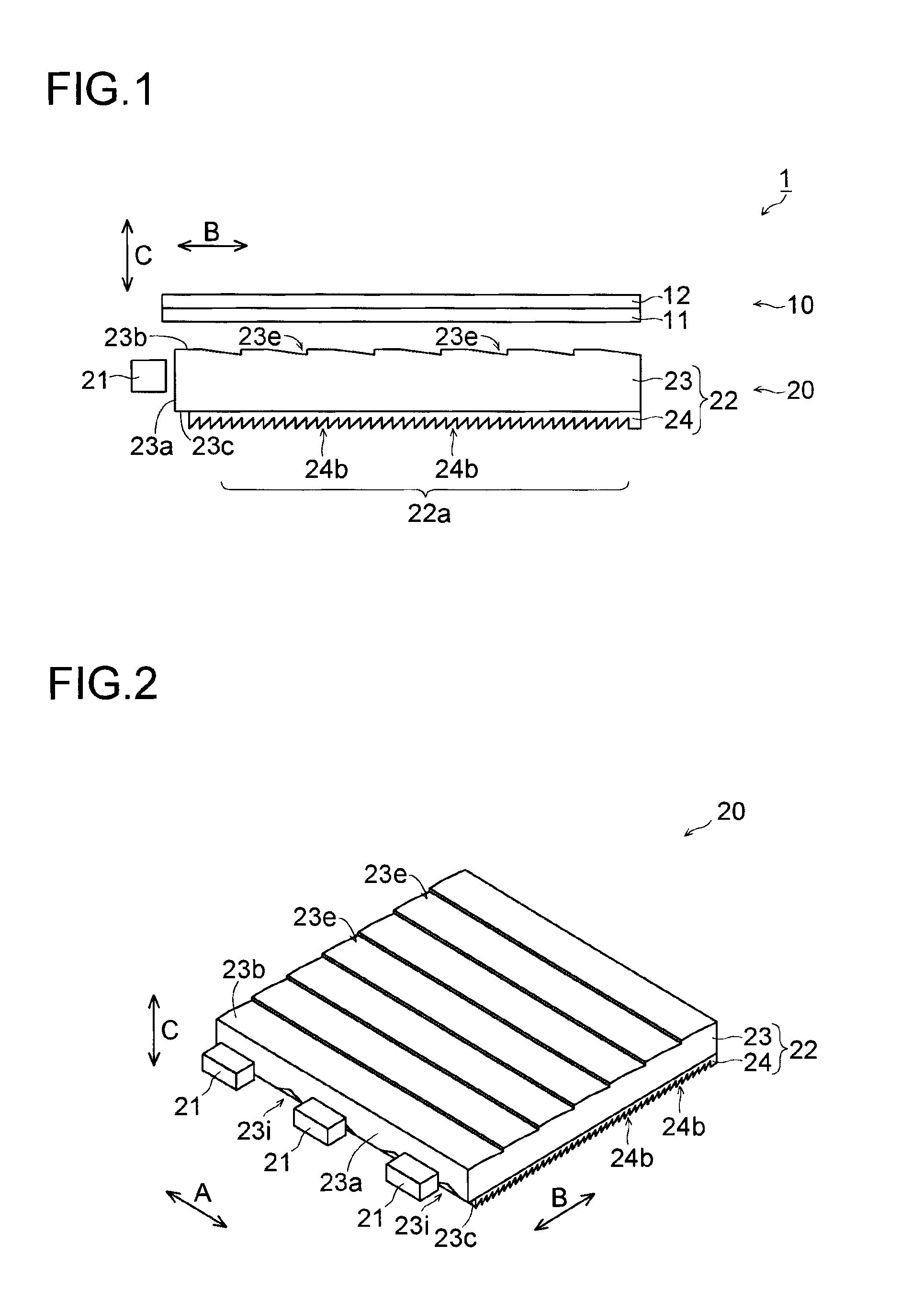
[0149]The structure of a liquid crystal display device 1 incorporating a backlight device 20 according to a first embodiment of the present invention will first be described with reference to FIGS. 1 to 6.
[0150]As shown in FIG. 1, the liquid crystal display device 1 according to the first embodiment of the present invention includes: a liquid crystal display panel 10; the backlight device 20 that is arranged on the side of the back surface of the liquid crystal display panel 10; and a frame (not shown) that accommodates the liquid crystal display panel 10 and the backlight device 20. The liquid crystal display device 1 is one example of a “display device” according to the present invention; the liquid crystal display panel 10 is one example of a “display panel” according to the present invention. The backlight device 20 is one example of a “planar illumination device” according to the present invention.
[0151]The liquid crystal display panel 10 includes: an AM substrate (active matri...
second embodiment
[0230]In the second embodiment, with reference to FIGS. 19 and 20, a description will be given of a case where, unlike the first embodiment, prisms 123e are formed on the back surface 123c of a light guide body 123.
[0231]In a backlight device 120 of the second embodiment of the present invention, as shown in FIG. 19, a light guide plate 122 is formed with: the light guide body 123 that has a light entering surface 123a which the light from the LEDs 21 enters; and a low refractive index layer 124 that has a lower refractive index than the light guide body 123. The backlight device 120 is one example of a “planar illumination device” according to the present invention; the light guide plate 122 is one example of a “light guide member” according to the present invention.
[0232]The light guide body 123 of the second embodiment is formed into the shape of a light guide body that is obtained by reversing the light guide body 23 of the first embodiment with respect to the C-direction.
[0233]...
third embodiment
[0242]In the third embodiment, with reference to FIGS. 21 and 23, a description will be given of a case where, unlike the first and second embodiments, prisms 223e and 223i are formed on the light emitting surface 223b of a light guide body 223.
[0243]In a backlight device 220 of the third embodiment of the present invention, as shown in FIGS. 21 and 22, a light guide plate 222 is formed with: the light guide body 223 that has a light entering surface 223a which the light from the LEDs 21 enters; and a low refractive index layer 224 that has a lower refractive index than the light guide body 223. The backlight device 220 is one example of a “planar illumination device” according to the present invention; the light guide plate 222 is one example of a “light guide member” according to the present invention.
[0244]In the third embodiment, as shown in FIG. 22, in the light emitting surface 223b of the light guide body 223, along the direction (B-direction) of the normal to the light enter...
PUM
 Abstract
Description
Claims
Application Information
 - R&D
- Intellectual Property
- Life Sciences
- Materials
- Tech Scout
- Unparalleled Data Quality
- Higher Quality Content
- 60% Fewer Hallucinations
Browse by: Latest US Patents, China's latest patents, Technical Efficacy Thesaurus, Application Domain, Technology Topic, Popular Technical Reports.
© 2025 PatSnap. All rights reserved.Legal|Privacy policy|Modern Slavery Act Transparency Statement|Sitemap|About US| Contact US: help@patsnap.com