Cooling member for heat containing device

Inactive Publication Date: 2011-12-08
TOYOTA MOTOR CO LTD
View PDF7 Cites 114 Cited by
  • Summary
  • Abstract
  • Description
  • Claims
  • Application Information

AI Technical Summary

Benefits of technology

[0008]A heat producing device can further be included, the heat producing device illustratively including a microprocessor, a power handling semiconductor device (e.g. a free wheeling diode, a metal-oxide-semiconductor field-effect transistor, reverse conducting insulated gate bipolar transistor, etc.), a microcontroller, application-specific integrated circuit (ASIC), a digital signal processor (DSP), a field-programmable gate array (FPGA) and the like. The heat producing component can have a first side with a first cooling member attached thereto and a second side with a second cooling member attached thereto. In addition, a first substrate can be located between the first cooling member and the first side of the heat producing device and a second substrate can be located between the second cooling member and the second side of the heat producing device. In some instances, the first substrate and / or second substrate can be a dielectric with direct bonded aluminum or direct bonded copper.

Problems solved by technology

However, heretofore cooling members have not taken full advantage of the structure or topology of the cooling member such that maximum cooling of the heat containing device occurs in a cost effective manner.

Method used


Image

  • Cooling member for heat containing device
  • Cooling member for heat containing device
  • Cooling member for heat containing device

Examples


embodiment 20

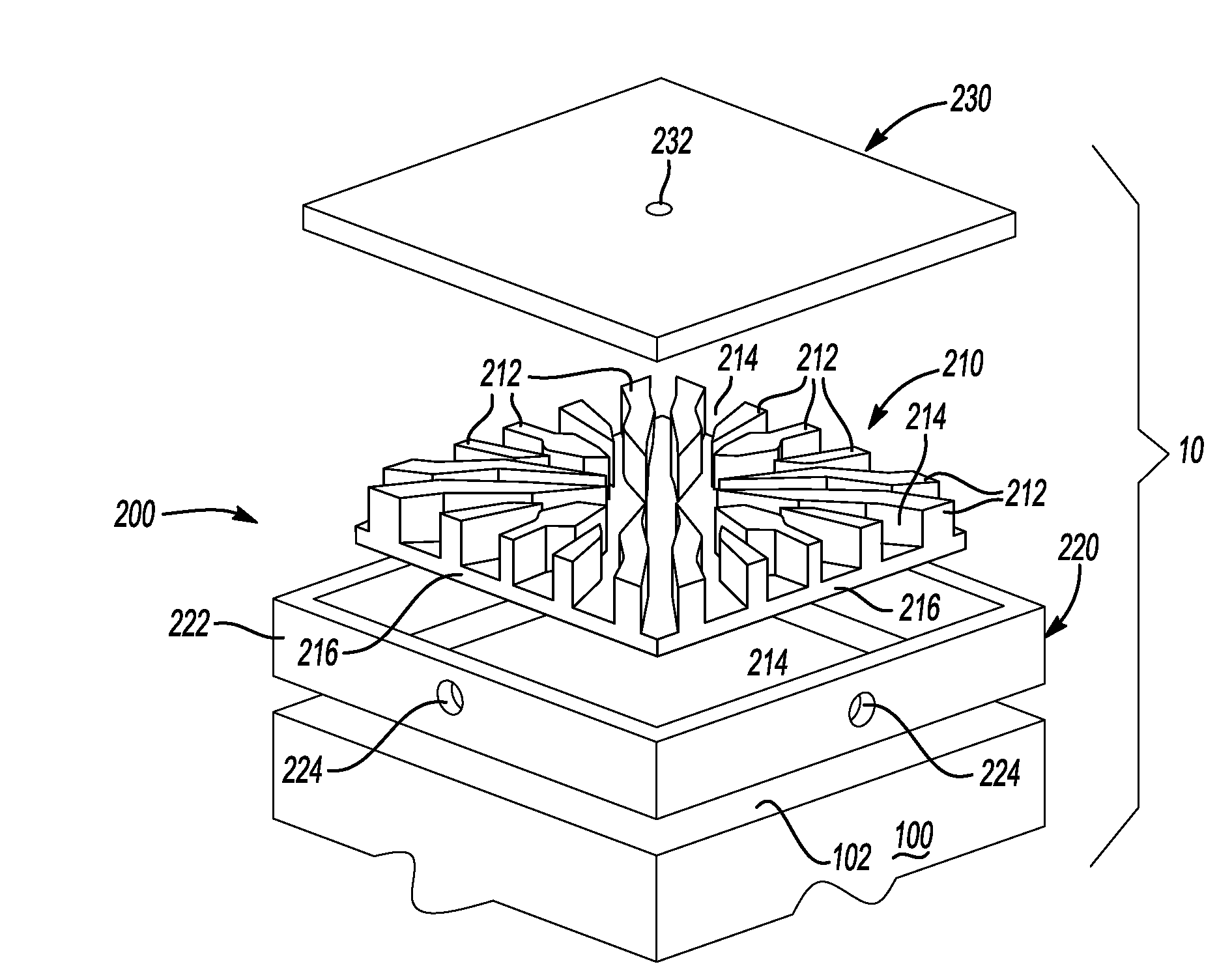
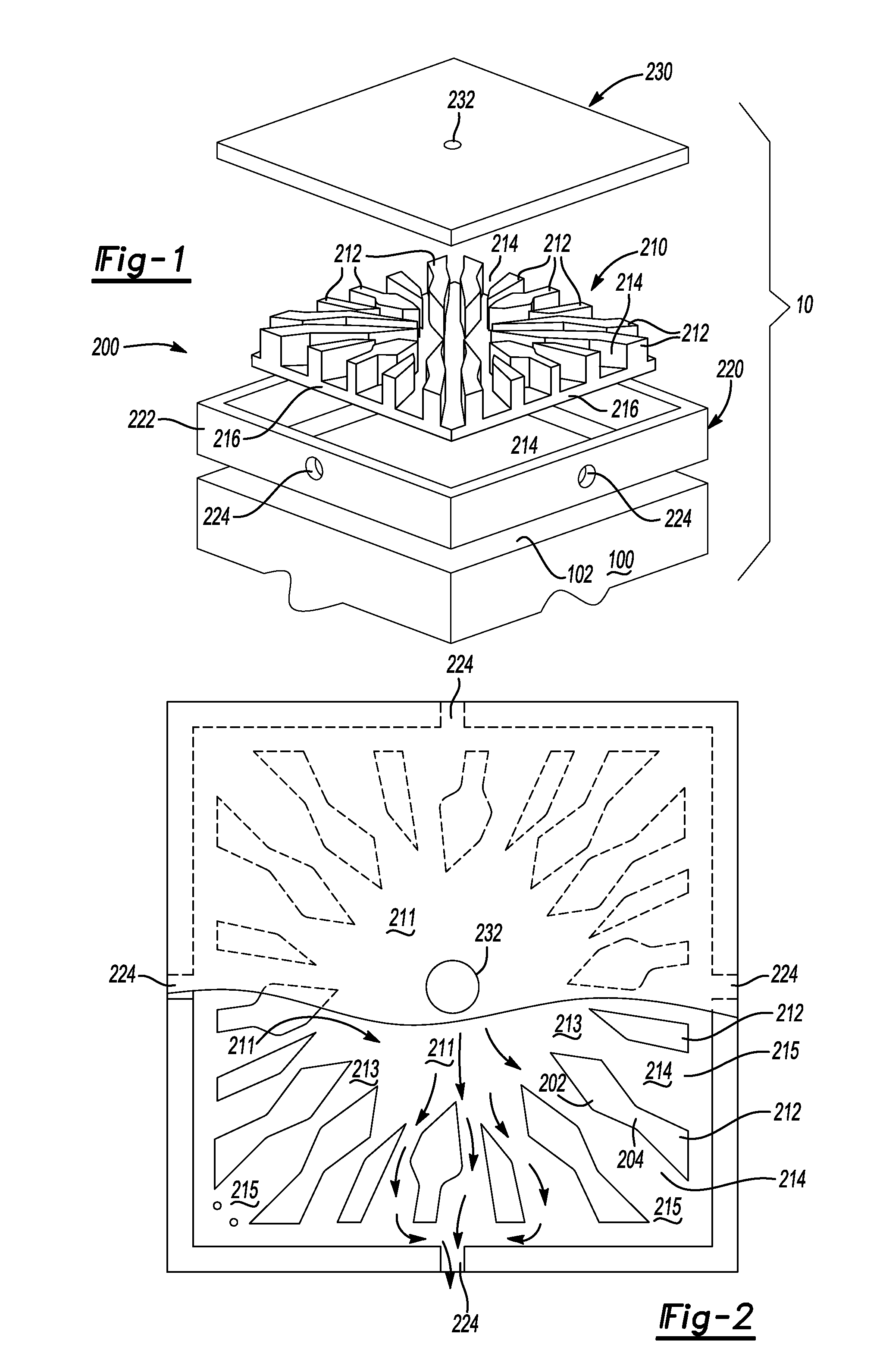
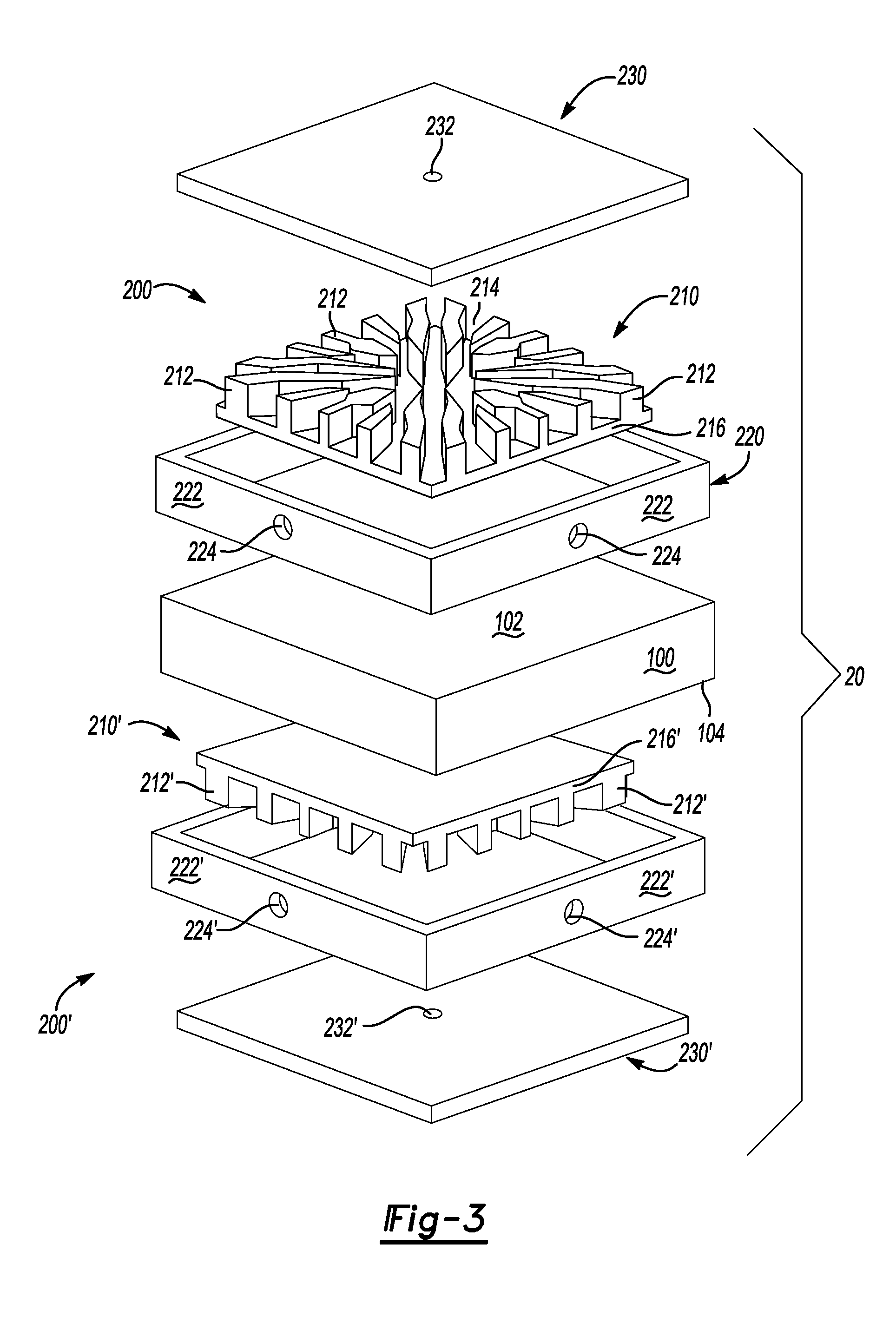
[0028]Turning now to FIG. 3, an embodiment 20 illustrates the heat containing device 100 having a first side 102 and a second side 104. The first side 102 can have a first cooling member 200 attached thereto and the second side 104 can have a second cooling member 200′ attached thereto. The second cooling member 200′ may or may not be generally identical to the first cooling member 200 based on the cooling requirements of the second side 104 relative to the first side 102. In this manner, the heat producing device 100 can have a double-sided cooling structure attached thereto, bonded thereto, integrally fabricated therewith, and the like.

embodiment 10

[0029]Similar to the embodiment 10 discussed above, a dielectric with DBA or DBC can be located between the heat producing device 100 and the cooling member 200, the cooling member 200′, the irregular-shaped fins 212 and / or the irregular-shaped fins 212′. In the alternative, a dielectric cooling fluid can be used without a dielectric located between the heat producing device 100 and the cooling member 200, the cooling member 200′, the irregular-shaped fins 212 and / or the irregular-shaped fins 212′.

embodiment 30

[0030]Turning now to FIG. 4, an embodiment 30 is shown where the heat containing device 100 is illustrated as an electronic device. For example and for illustrative purposes only, the heat producing device 100 can be an RC-IGBT. The device 100 can have a substrate 120 with device active region 122 and one or more sensor and / or control terminals 124. In addition, a substrate 130 can be attached to the substrate 120 and / or active region 122 and have a lead 132 to a motor and / or generator, a lead 134 to a battery, and one or more leads 136 to a gate / driver / controller. Attached to at least one side of the device 100 can be a cooling member 200 as described above. In the alternative, a layer or panel of DBA or DBC 140, a dielectric layer or panel 142 and / or a second layer or panel of DBA or DBC 144 can be located between the substrate 130 and the cooling member 200 and / or irregular-shaped fins 212. In this manner, an electronic power device can be cooled using a cooling member designed a...


PUM


Abstract

A cooling member for withdrawing heat from a heat containing device is disclosed. The cooling member can have a housing with a fluid inlet, a fluid outlet and a plurality of irregular-shaped fins located at least partially therewithin. In addition, a plurality of irregular-shaped and hierarchical branched fluid pathways can be located between the plurality of fins and the housing and/or the plurality of fins can be in physical contact with the heat containing device.

Description

FIELD OF THE INVENTION[0001]The present invention is related to a cooling member for withdrawing heat from a device containing heat. In particular, the present invention is directed to a cooling member that has a plurality of irregular-shaped and hierarchical branched fluid pathways.BACKGROUND OF THE INVENTION[0002]Heat is known to be generated by a variety of machines and devices such as electronic devices, electronic circuitry, internal combustion engines, etc. For such devices, heat is typically dissipated therefrom in order to improve reliability and prevent premature failure. Techniques, apparatus, etc., for heat dissipation can include heat sinks, fans for air cooling, liquid cooling, radiators, heat pipes, etc. In some instances, fluid can be forced through a cooling member that is in physical contact with and / or attached to the device in order to dissipate or remove heat. However, heretofore cooling members have not taken full advantage of the structure or topology of the co...

Claims


Application Information

Patent Timeline
Patent Type & Authority Applications(United States)
IPC IPC(8): H05K7/20H01L29/739F28F7/00
CPCF28F3/046F28F13/08H01L23/473H05K7/20254H01L2924/0002F28F2215/04H01L2924/00F28F2210/02
Inventor DEDE, ERCAN MEHMETROBERT, BRIAN JOSEPHYONAK, SERDAR H.
Owner TOYOTA MOTOR CO LTD
Why Eureka
Try Eureka