Speaker polarity determination device

a technology of polarity determination and speaker, which is applied in the direction of electrical equipment, etc., can solve the problems of deteriorating reproduction quality

Active Publication Date: 2011-12-08
ONKYO TECH KK
View PDF5 Cites 14 Cited by
  • Summary
  • Abstract
  • Description
  • Claims
  • Application Information

AI Technical Summary

Benefits of technology

[0008]The present invention is made to solve the above-mentioned problem. It is an object of th...

Problems solved by technology

When the speaker is negatively connected, the phase of the sound outputted...

Method used


Image

  • Speaker polarity determination device
  • Speaker polarity determination device
  • Speaker polarity determination device

Examples


embodiment

[0038]A preferred embodiment of the present invention will be described below with reference to the attached drawings.

[0039][Apparatus Configuration]

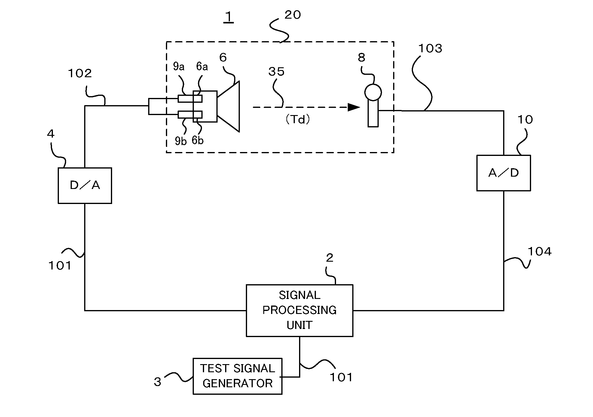
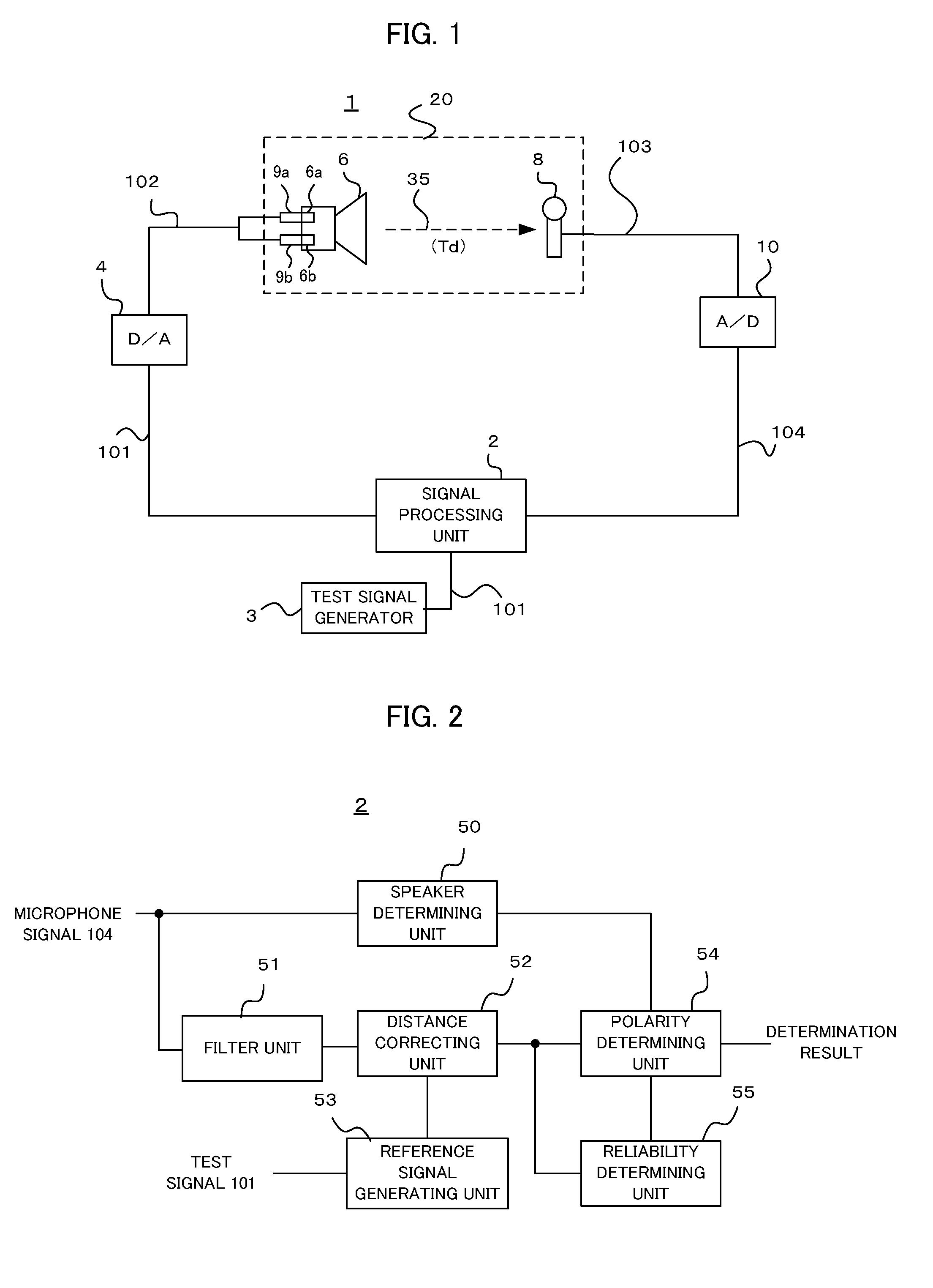
[0040]FIG. 1 illustrates a schematic configuration of an acoustic apparatus 1 to which a speaker polarity determination device according to the present invention is applied. The acoustic apparatus 1 is connected with a speaker 6, and a sound signal from a sound source not shown, such as a CD or DVD, is reproduced via the speaker 6. It is noted that the speaker polarity determination described below is performed when the speaker 6 is connected to the acoustic apparatus 1, prior to reproduction from the sound source .

[0041]The acoustic apparatus 1 includes a signal processing unit 2, a test signal generator 3, a D / A converter 4, a microphone 8, output terminals 9 to which the speaker 6 is connected, and an A / D converter 10 . The speaker 6 and the microphone 8 are arranged in an acoustic space 20. The acoustic space 20 may be a listening r...


PUM


Abstract

A speaker determination device determines a polarity of a speaker connected to output terminals. Test sound is outputted to an acoustic space via the connected speaker and is collected by a microphone. A reference signal is generated based on the test signal. A polarity determining unit compares predetermined frequency range components of the microphone signal obtained by the microphone and the reference signal, and determines the polarity of the speaker, i.e., whether the speaker is connected in positive phase or in negative phase.

Description

TECHNICAL FIELD[0001]The present invention relates to a technique of determining polarity of speakers in an apparatus which outputs sound via the speakers.BACKGROUND TECHNIQUE[0002]There is known an acoustic apparatus, such as an audio product and a home theater product, which is connected with speakers and outputs sound. When speakers are connected to such an apparatus, it is normally necessary to connect a plus (+) terminal and a minus (−) terminal to a plus terminal and a minus terminal of output terminals of the apparatus, respectively. It is called that speaker polarity is positive when the plus terminals and the minus terminals are correctly connected. In contrast, it is called that speaker polarity is negative when the plus terminals and the minus terminals are reversely connected.[0003]When the speaker is negatively connected, the phase of the sound outputted by the speaker is reversed, and generally reproduction quality is deteriorated. Therefore, there is proposed a techni...

Claims


Application Information

Patent Timeline
IPC IPC(8): H04R29/00
CPCH04R29/00
Inventor YOSHINO, HAJIME
Owner ONKYO TECH KK
Why Eureka
Try Eureka