Waterproof structure for a cable connector, and a plug connector, socket connector and cable connector utilizing the same

a technology of waterproof structure and cable connector, which is applied in the direction of coupling/insulating coupling contact members, coupling device connections, coupling bases/cases, etc., can solve the problems of unavoidable cases where the length of necessary cables must be changed and the installation must be suspended, so as to facilitate the installation of a cable connector and reliably prevent the penetration of liquid inside the cable connector

Active Publication Date: 2011-12-08
YAMAICHI ELECTRONICS
View PDF6 Cites 25 Cited by
  • Summary
  • Abstract
  • Description
  • Claims
  • Application Information

AI Technical Summary

Benefits of technology

[0010]In view of the above-described mentioned problem, the present invention aims to provide a waterproof structure for a cable connector, and a plug connector, socket connector and cable connector that uses the same. The waterproof structure for a cable connector, and a plug connector, socket connector and cable connector that uses the same can easily attach a cable connector to one end of a cable without the need for molding while at the same time reliably preventing the penetration of liquid inside the cable connector.
[0016]According to the waterproof structure for a connector cable of the present invention, and a plug connector, socket connector and cable connector utilizing the same, it is possible to easily attach a cable connector to the end of a cable without the need for molding because the housing detachably houses the contact terminal to which the end of the cable is attached.
[0017]Furthermore, because a sealing cylinder is provided that holds a sealing tube, mounted on the outside of the cable inserted into the housing, inside a plurality of pressing pieces, and a pressing member presses, in the case where the contact terminal having an end of the cable connected thereto is received in the housing, the plurality of pressing pieces of the sealing cylinder, along with the sealing tube, towards the outer periphery of the cable inside the housing, it is possible to reliably prevent the penetration of liquid inside the cable connector.

Problems solved by technology

However, upon installation, there are unavoidable cases where the length of necessary cable must be changed, due to, for example, a change of the installation position of the photovoltaic modules at the site.
Thus, because of the difficulty of manufacturing, at the site, a subassembly wherein the above described connector is connected to the end of a cable, a problem occurs wherein installation must be suspended until the new cable can be prepared.

Method used


Image

  • Waterproof structure for a cable connector, and a plug connector, socket connector and cable connector utilizing the same
  • Waterproof structure for a cable connector, and a plug connector, socket connector and cable connector utilizing the same
  • Waterproof structure for a cable connector, and a plug connector, socket connector and cable connector utilizing the same

Examples


Embodiment Construction

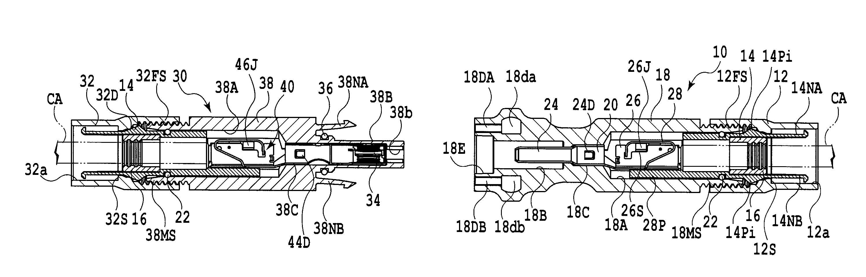
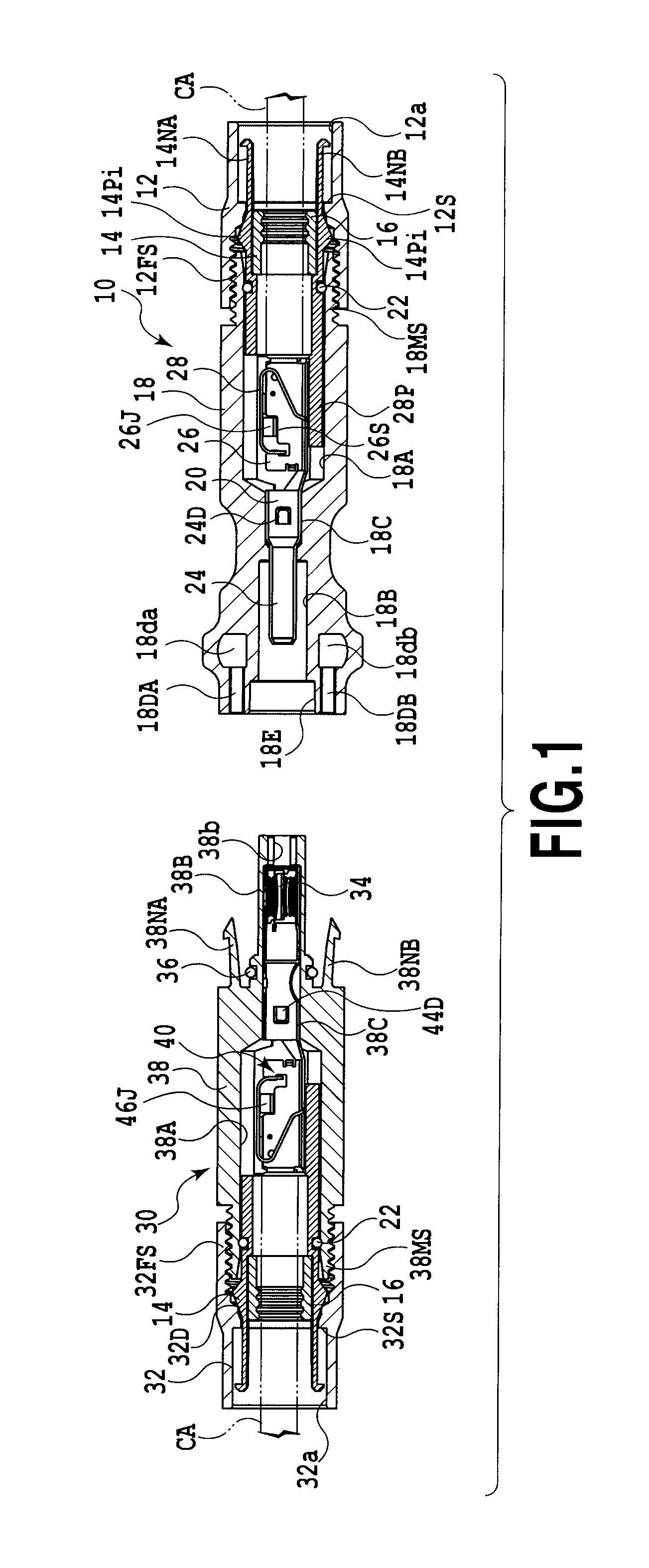
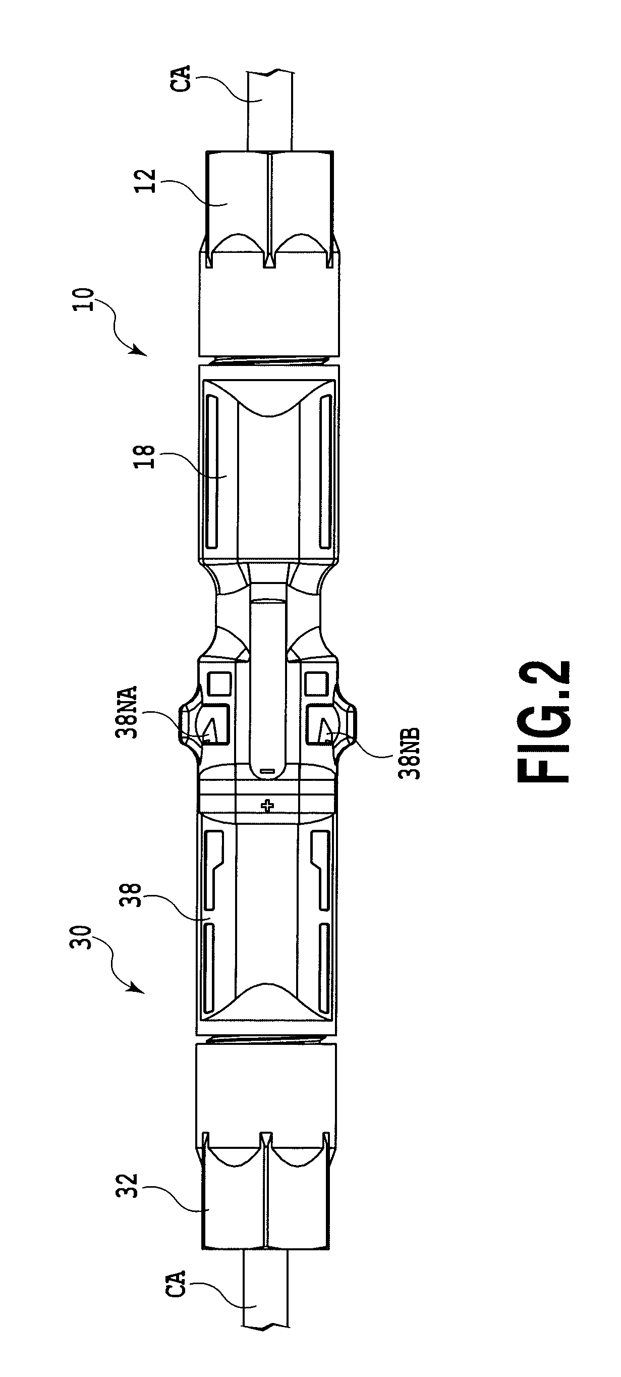
[0031]FIG. 2 illustrates an external view of a cable connector that utilizes an example of a waterproof structure for a cable connector according to the present invention. Regarding the cable connector, it should be noted that in FIG. 2 the later described socket connector and plug connector are shown in a connected state.

[0032]The cable connector shown in FIG. 2 is to be attached, for example, to both ends of a cable that mutually connects photovoltaic modules, to the ends of a cable that connects between a photovoltaic module and a power switchboard, or to the ends of a cable that connects between a free hanging type connector and a photovoltaic module.

[0033]In FIG. 2 the cable CA is, for example, a cable for connecting solar modules (Model KSK-, manufactured by Kaneko Cord Co.), comprising a single-core internal conductor, a cross-linked polyethylene insulator that clads the internal conductor, and a flame resistant cross-linked polyethylene sheath that sheathes the internal cond...


PUM


Abstract

In the case where the cable CA is passed through the hole of the sealing tube and connected to the plug contact terminal and the socket contact terminal, when the female threaded portions and of the stepped pressure nut members and are respectively screwed onto the male threaded portions and of the plug housing and the socket housing, the outer periphery of the cable CA inside the plug housing and the socket housing is sealed by way of the pressing pieces and the sealing tube being pressed.

Description

CROSS-REFERENCES TO THE RELATED APPLICATIONS[0001]This application claims the benefit of Japanese Patent Application No. 2010-131124 filed Jun. 8, 2010, which is hereby incorporated by reference herein in its entirety.BACKGROUND OF THE INVENTION[0002]1. Field of the Invention[0003]The present invention relates to a waterproof structure for a cable connector, and a plug connector, socket connector and cable connector utilizing the same.[0004]2. Description of the Related Art[0005]Waterproof cable connectors have generally been made available for practice that electrically connect between photovoltaic modules or between a solar power generation module and a power switchboard. These types of cable connectors, as shown in Japanese Patent Laid-open No. 2002-298656 for example, are configured to include a male terminal fitting as a contact terminal, a sealing tube that covers the wire crimping portion of the male terminal fitting and the insulating jacketing of the cable, and a housing jo...

Claims


Application Information

Patent Timeline
Patent Type & Authority Applications(United States)
IPC IPC(8): H01R13/52
CPCH01R13/6273H01R13/5219
Inventor SOMEYA, TOSHIYUKI
Owner YAMAICHI ELECTRONICS
Why Eureka
Try Eureka