Mortar and debris collection system

a collection system and debris technology, applied in the field ofmortar and debris collection devices, can solve the problems of inability to collect mortar and debris, and achieve the effect of enhancing hydrophobic properties

Inactive Publication Date: 2011-12-15
SOURLIS TOM
View PDF3 Cites 38 Cited by
  • Summary
  • Abstract
  • Description
  • Claims
  • Application Information

AI Technical Summary

Benefits of technology

[0011]Accordingly, it is an objective of this invention to provide an improved mortar and debris collection device that can protect one or more weep holes preventing mortar or debris of any significant size from reaching a weep hole and thereby blocking the holes, which is not negatively affected by water.
[0012]Another objective is to provide a surface configuration for such a collection device which facilitates adequate dispersal of debris thereon to assure a water path remains to the collection device.
[0016]A preferred form of the collection device has upwardly extending protrusions, such as protrusions defining overhangs as well as steps, which serve to break up mortar and debris falling on top of the collection device. This prevents ponding of the material on the surface of the collection device.
[0018]There are many and sundry ways to make the water-permeable debris-catching body. However, according to a central feature of the invention, one or all of the inventive collection device, mesh block, porous mesh, screens and related structures, for example, perhaps including weep hole bodies and flashing, pans, trays and so on, are formed of, treated with, or coated by materials having enhanced hydrophobic properties.

Problems solved by technology

Water can migrate through the porous mass to a drain outlet, such as the weep holes, but mortar and debris cannot.

Method used


Image

  • Mortar and debris collection system
  • Mortar and debris collection system
  • Mortar and debris collection system

Examples


first embodiment

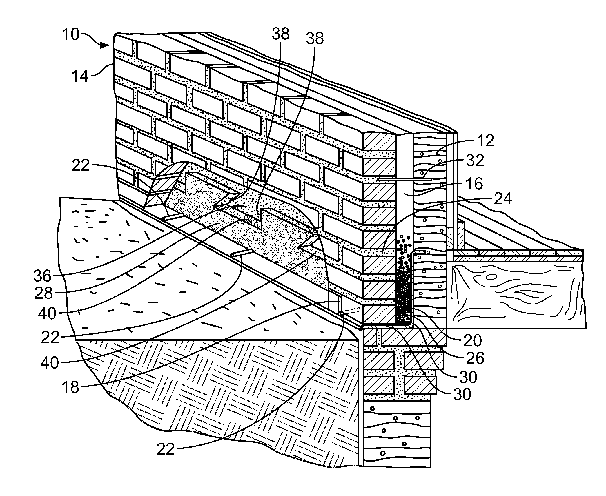
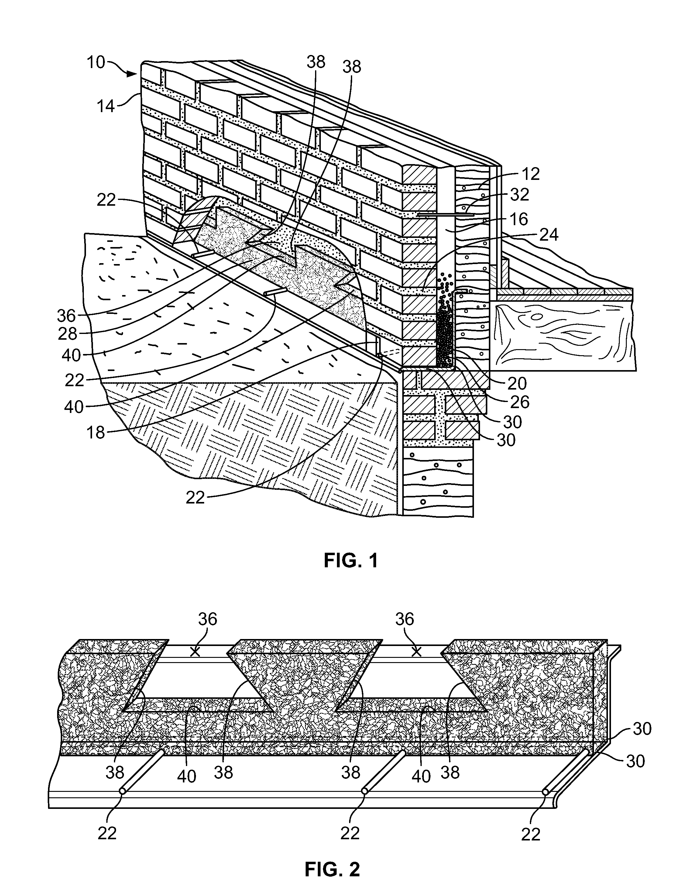
[0094]Referring to FIG. 13 there is shown yet another embodiment of the invention wherein the same reference numerals from the first embodiment followed by a double prime sign are used to identify common elements. Device 120″ includes a strip of material 132″ adjacent the intersection of the central portion 136″ and the lower portion 138″. A plurality of spaced apart tubes or channels 146 are formed in the upper surface of lower portion 138″ extending about to lip 144″ to create the weep holes within the mortar joint. The tubes or channels 146 alternatively may be integrally formed as a separate member or members positioned immediately adjacent the upper surface of portion 138″. The tubes or channels 146 may be positioned over mesh strips 142 as shown in FIG. 11.

[0095]Referring to FIG. 14, there is shown still another embodiment of the invention wherein the same reference numerals from the first embodiment followed by a triple prime sign are used to identify common elements. Device ...

embodiment 730

[0156]One feature of the illustrated embodiment 730 is that the drip edge 744 extends to a point 745 less than the terminus or end 747 of the flashing lower portion 740. This creates an overlapping portion or tab 749, preferably having a length of about 2 to 4 inches to overlap with an adjacent flashing member and the overlap may include a mesh drainage strip 717 preferably of enhanced hydrophobic material. Preferably, the vertical body 736 adjacent the end 747 is aligned with the end 745 of the drip edge 744. The vertical body 736 also preferably has a termination bar 756 along an upper edge thereof as in an above-detailed embodiment.

[0157]FIG. 36 shows yet another embodiment of the flashing and drainage system 830 according to the invention. The generally top-down view shows the system 830 flashing member 832. The flashing member 832 is a flattened sheet-like material sized and shaped to be used, for example, within a cavity wall 10 and more particularly in a building joint, such ...


PUM

PropertyMeasurementUnit
lengthaaaaaaaaaa
heightaaaaaaaaaa
lengthaaaaaaaaaa

Abstract

Mortar and debris collection systems for cavity wall construction and / or walls constructed from concrete masonry units (CMU), for example, include a mesh body made of a material that is formed with circuitous paths therethrough making the body water-permeable. The mesh body is formed of a material having enhanced hydrophobic properties. The mesh body has a porosity sufficient to permit water to pass therethrough but insufficient to permit mortar and other debris to pass therethrough to weep holes or other water channels covered by the collection debris.

Description

FIELD OF THE INVENTION[0001]This invention generally relates to mortar and debris collection devices, such as are used in association with cavity wall and other types of wall construction. To illustrate, in the course of construction of a masonry cavity wall for example, mortar and other debris falls into the cavity, and may then block weep holes or other water outlets necessary to prevent moisture build-up within the wall cavity. This invention more specifically relates to a device and system for collecting loose mortar and other debris in order to prevent the same from blocking the weep holes that ventilate such a cavity wall. The invention is also applicable to other types of wall construction, such as, for example, walls made of concrete masonry units (CMUs). Moreover, the invention is directed to devices for managing water in various types of wall construction having a mesh body and related structures being formed of materials with enhanced hydrophobic properties.BACKGROUND OF ...

Claims


Application Information

Patent Timeline
Patent Type & Authority Applications(United States)
IPC IPC(8): E02D19/00
CPCE02D19/00
Inventor SOURLIS, TOM
Owner SOURLIS TOM
Why Eureka
Try Eureka