

Nail printer and print controlling method
a printing method and nail technology, applied in the field of nail printers, can solve the problems of taking a lot of time and effort, design or pattern cannot be printed successively on the nails of both groups of fingers or both thumbs of both the user's right and left hands,
- Summary
- Abstract
- Description
- Claims
- Application Information
AI Technical Summary
Benefits of technology
Problems solved by technology
Method used
Image

Examples
first embodiment
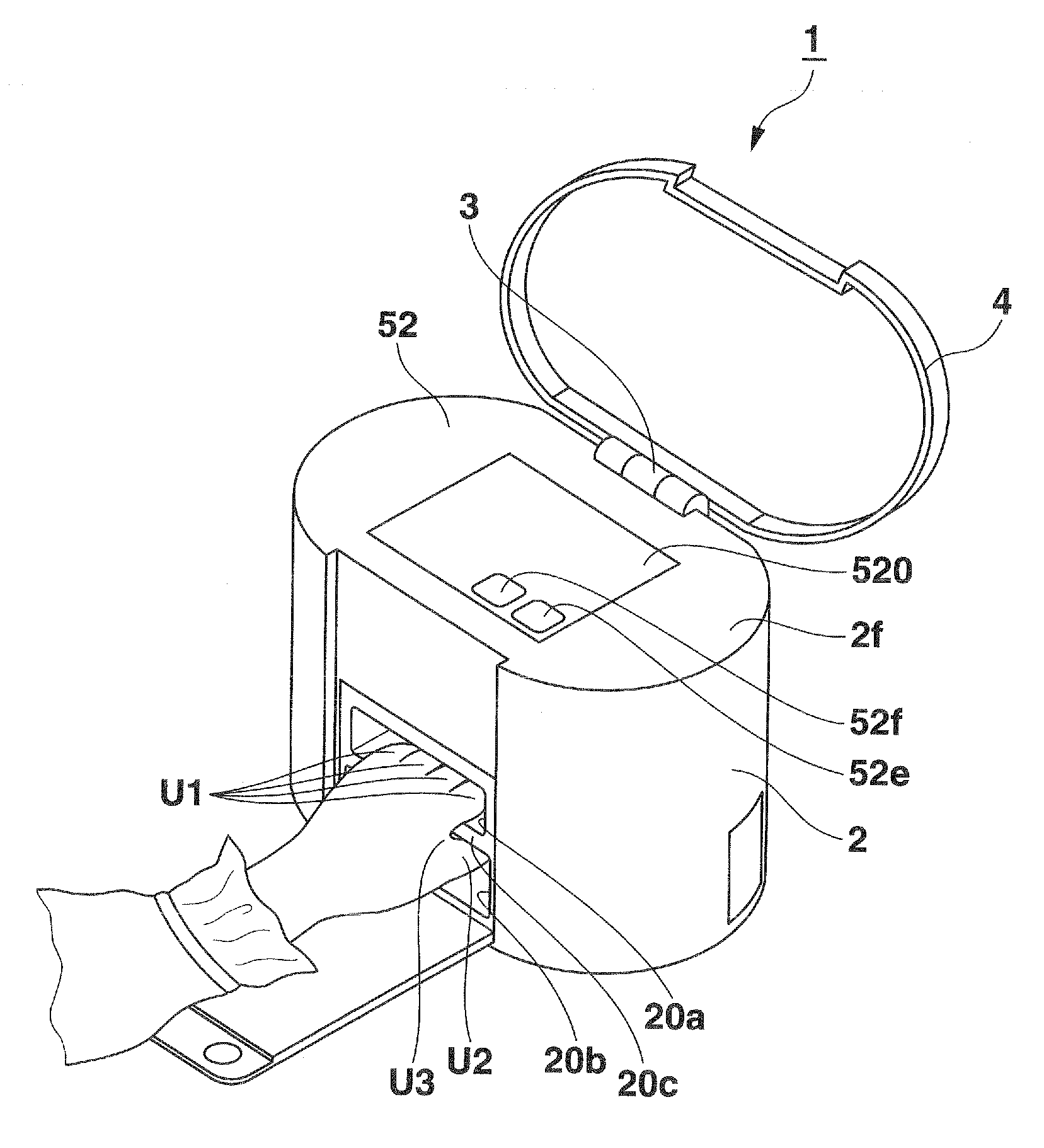
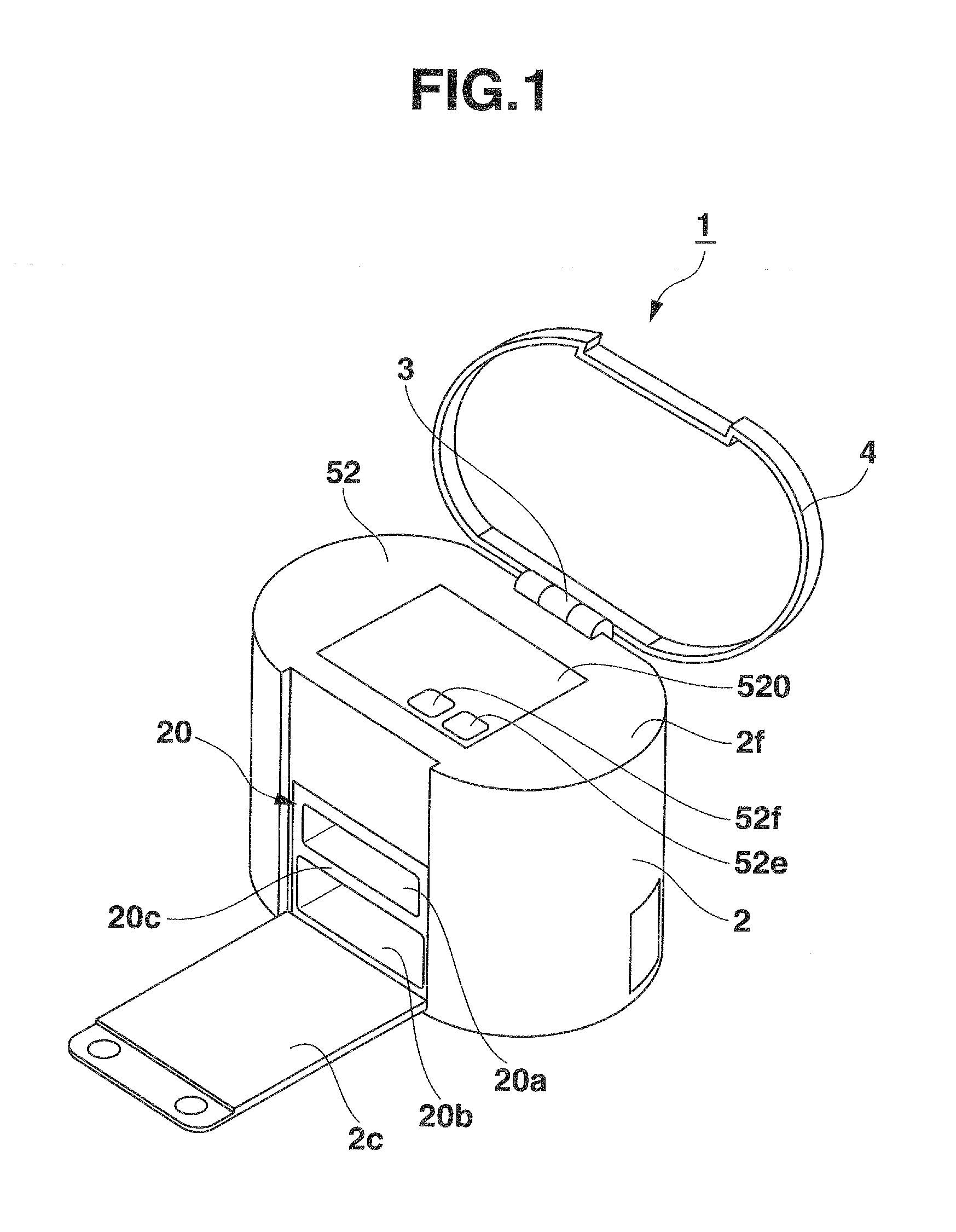
[0024]Referring to FIGS. 1-10, a first embodiment of a nail printer according to the present invention will be described. As shown in FIG. 1, the nail printer 1 is comprised of a case 2 substantially elliptical in plan view and a top cover 4 hinged at 3 to a top rear edge of the case 2. The case 2 also has an openable front cover 2c hinged at its lower end to a front lower end of the case 2. A control panel 52 is provided substantially at the center of a top 2f of the case 2 so as to cover the top of the case 2. The shapes of the case 2 and the top cover 4 are not limited to the illustrated ones.
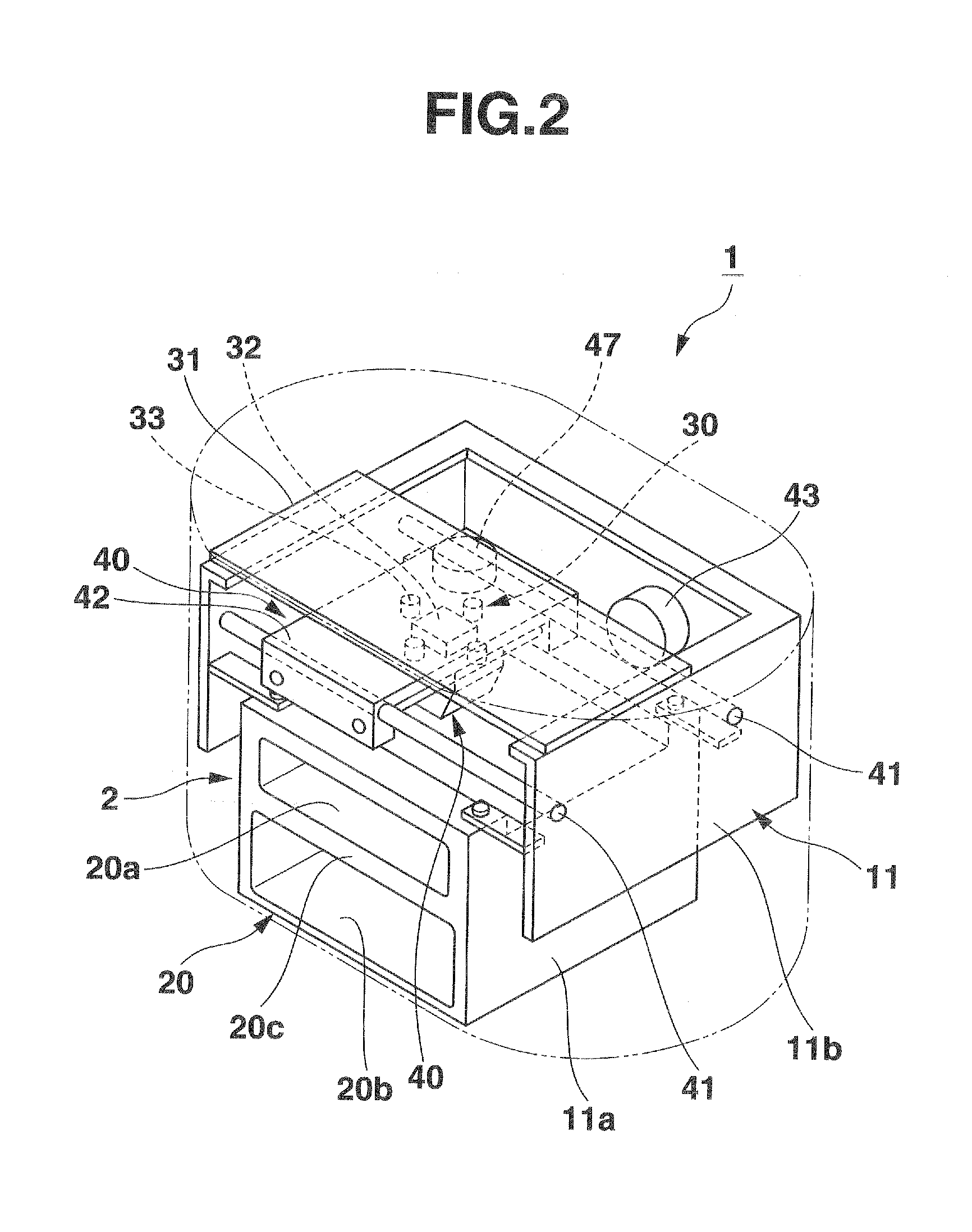
[0025]The case 2 encases a printer body 10 which comprises a finger holder 20, an image catcher 30, a printing unit 40, and a controller 50 as control means (FIG. 8) provided on a frame. The frame is comprised of a lower box-like sub-frame 11a disposed at a lower position within the case 2 and an upper sub-frame 11b disposed over the lower frame 11a at an upper position within the case 2.
[00...
second embodiment
[0055]The second embodiment of the nail printer according to the present invention will be described. The second embodiment is different in printing process from the first embodiment and its different points will be mainly described. The nail printer of this second embodiment has a substantially similar structure to the first embodiment.
[0056]In the second embodiment, the control sub-unit 51 functions as control means for controlling the printing unit 40 and other devices concerned as in the first embodiment. More specifically, when receiving a command from the print switch 52e alone as the second print start commanding means, the control sub-unit 51 controls the print controlling means (including the image catcher 30 and the printing unit 40) so as to start to print on the respective nails T immediately. On the other hand, when receiving a command from the both-hand switch 52f as the first print start commanding means and then a command from the print switch 52e as the second print...
third embodiment
[0064]Then, the third embodiment of the nail printer according to the present invention will be described. In the embodiment, the control panel is different in structure from those of the first and second embodiments. In the following, their different points will be described. The nail printer of this embodiment has a similar structure to those of the first and second embodiments.
[0065]FIG. 12 is a plan view of a control panel 72 of the nail printer of the present embodiment. The control panel includes a top-side control sub-panel 72A provided on a top of the case and a cover-side control sub-panel 72B provided on the back of the top cover.
[0066]The top-side control sub-panel 72A has a power source button 72a that turns on the power source of the nail printer 1, and a stop button 72e that stops the nail printer, a plurality of numerical buttons 72c, a decision button 72d, a print button 72e, a both-hand button 72f and others.
[0067]The cover-side control sub-panel 72B comprises a liq...
PUM
 Abstract
Description
Claims
Application Information