
Thermal printer

a technology of thermal printers and thermal printers, applied in the direction of printing, power drive mechanisms, instruments, etc., can solve the problems of increasing cost, difficulty in efficient production, and the like, and achieve the effect of improving the attaching property, facilitating the fixing operation of biasing members and flexible substrates

Inactive Publication Date: 2008-10-28
SEIKO INSTR INC
View PDF2 Cites 7 Cited by
  • Summary
  • Abstract
  • Description
  • Claims
  • Application Information

AI Technical Summary

Benefits of technology

[0010]The present invention has been made in view of the above-mentioned circumstances, and an object of the present invention is to provide a thermal printer which enables electrostatic to be positively let out without a provision of a dedicated conducting component which is an essential component in a conventional thermal printer, enables efficient production without requiring much time and effort, and enables a reduction in cost.

Problems solved by technology

Incidentally, the thermal head and the recording paper are constantly in contact with each other, and during printing in particular, the thermal head and the recording paper cause friction, so electrostatic is accumulated in the thermal head.
However, the conventional thermal printer still has the following problems.
Accordingly, production thereof requires much time and effort and costs for the conducting components have been required, thereby leading to an increase in cost and difficulty in efficient production.

Method used


Image

  • Thermal printer
  • Thermal printer
  • Thermal printer

Examples


Embodiment Construction

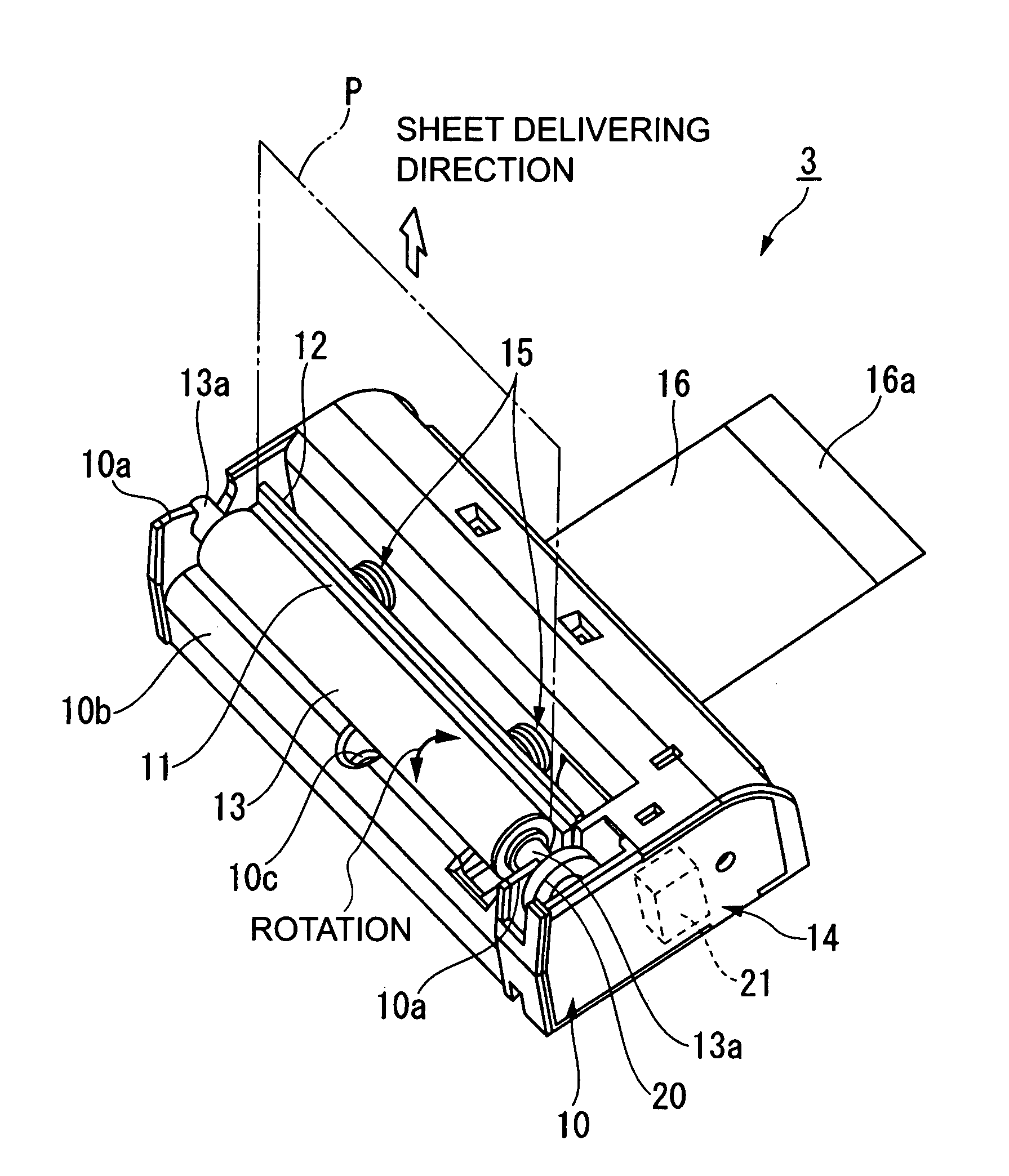
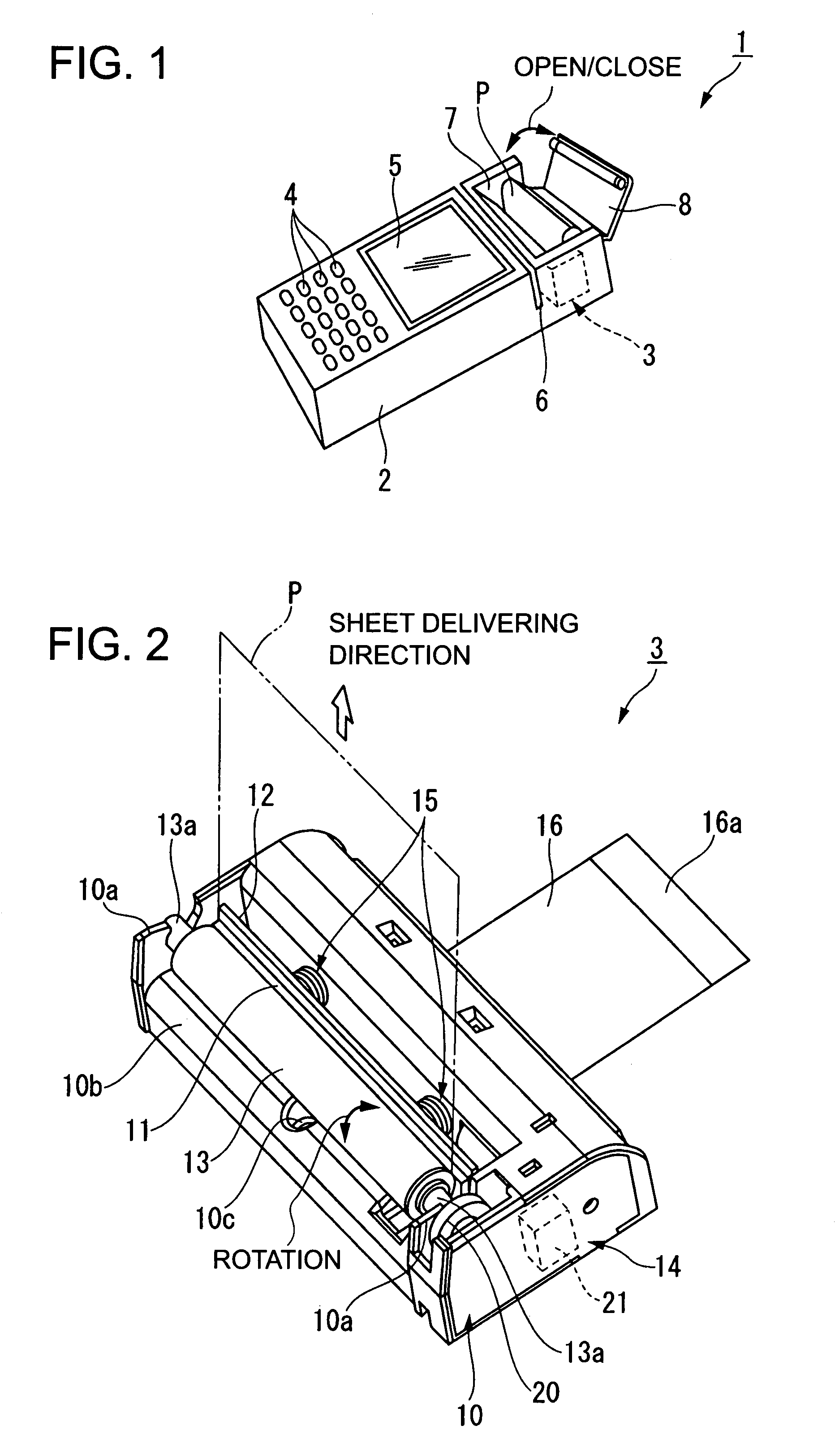
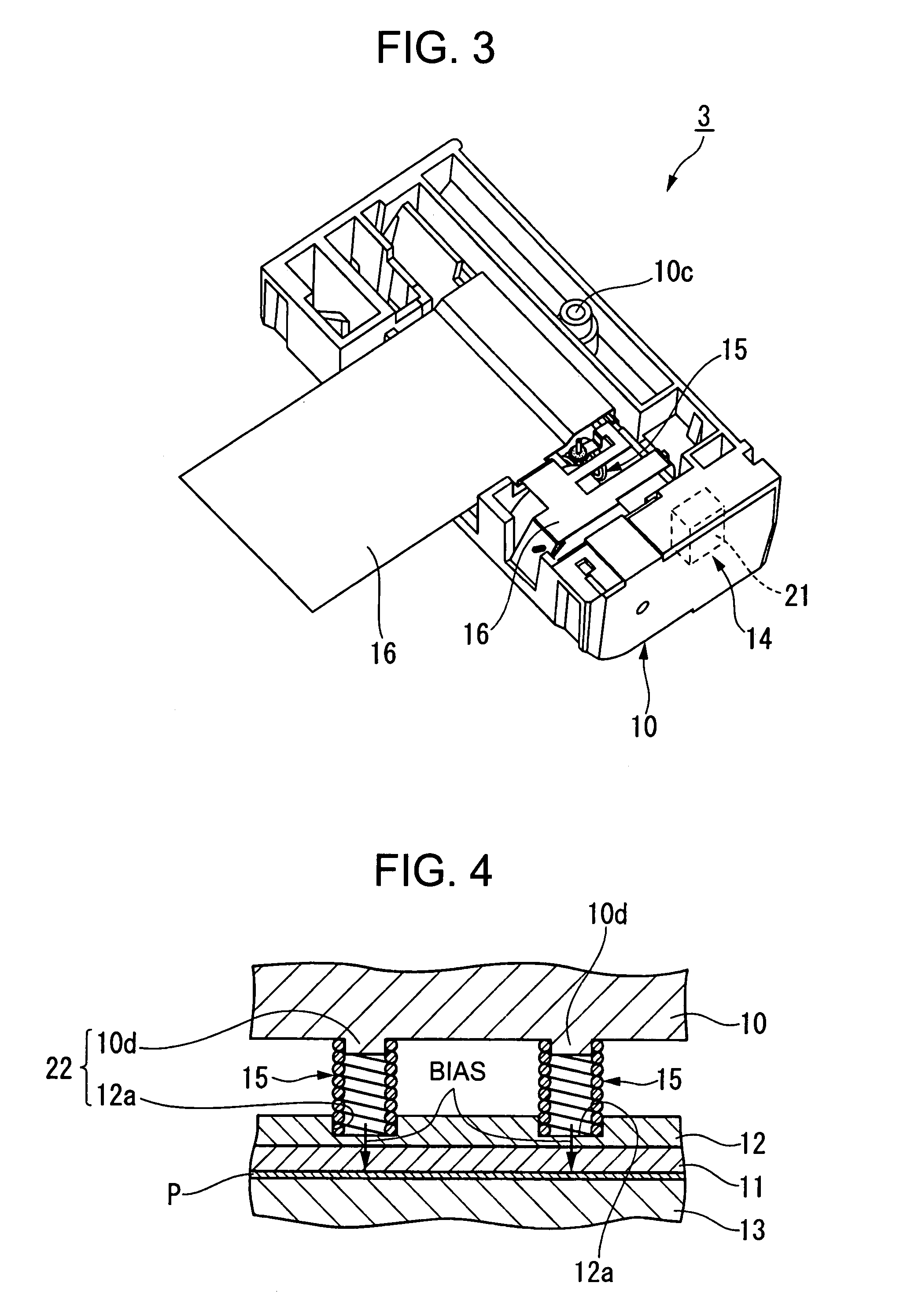
[0037]Hereinafter, an embodiment of a thermal printer according to the present invention will be described with reference to FIGS. 1 to 6. It should be noted that in this embodiment, an example of a case where a thermal printer is mounted to a portable information terminal capable of allowing a home-delivery worker to perform card settlement at a client site is described.

[0038]As shown in FIG. 1, an information terminal 1 of this embodiment includes a case body 2, a thermal printer 3 accommodated in the case body 2, an input portion 4 composed of a plurality of key buttons and a liquid crystal display portion 5 for displaying various sorts of information, both of which are provided on a surface of the case body 2, a reading portion 6 for reading data from a magnetic recording portion of a magnetic card (not shown) at a time of insertion of the magnetic card, a recording paper accommodating portion 7 for accommodating a recording paper P wound in a roll, and a cover 8 which supports ...


PUM


Abstract

Provided is a thermal printer including: a thermal head having a plurality of heating elements; a head support member, which is conductive, for supporting the thermal head; a platen roller whose circumferential surface can be brought into contact with the thermal head while nipping a recording paper; biasing members, which are conductive, provided between the case and the head support member, for supporting the head support member while imparting bias toward the platen roller; and a flexible substrate electrically connected with the thermal head to transmit a signal, in which a part of the biasing member extends through the flexible substrate and is grounded by fixation while being electrically connected by solder with respect to the flexible substrate.

Description

BACKGROUND OF THE INVENTION[0001]1. Field of the Invention[0002]The present invention relates to a thermal printer incorporated in various kinds of portable information equipment, for performing printing by pressing a heat-generating thermal head against a recording paper.[0003]2. Description of the Related Art[0004]As to a thermal printer mounted to a portable information terminal or the like, for performing printing by pressing a heated thermal head against a special recording paper whose color changes when applied with heat, various models are currently on the market in large quantity. In particular, such the thermal printer is suitably used for printing various kinds of labels, receipts, tickets, and the like because the thermal printer can print characters with smooth outlines as well as multicolor graphics without using toner, ink, or the like.[0005]In general, the thermal printer includes a thermal head having a plurality of heating elements, ahead support member for supporti...

Claims


Application Information

Patent Timeline
Patent Type & Authority Patents(United States)
IPC IPC(8): B41J25/304
CPCB41J2/325
Inventor TOZAKI, SHUJI
Owner SEIKO INSTR INC
Learn More