Stapler that requires exertion of less effort

a technology of staplers and staplers, applied in the field of staplers, can solve the problems of inconvenient use, large angle of movement of the transmitting shaft or the eccentric wheel of the prior art, and frequent incidents of staples being popped out or staples being driven in the wrong position, so as to reduce the time for stapling and resetting, and the effect of less time and effor

Inactive Publication Date: 2008-06-24
COSIMEX H K
View PDF6 Cites 9 Cited by
  • Summary
  • Abstract
  • Description
  • Claims
  • Application Information

AI Technical Summary

Benefits of technology

[0005]In view of the aforesaid disadvantages now present in the prior art, the object of the present invention is to provide an electric stapler which is of a simple and practical construction, has components for rotation with a smaller angle of movement, requires less time for stapling and resetting, requires less time and effort for operation, and is capable of ensuring the consistency of the stapling quality.
[0010]The gear cluster comprises 1 driving gear and 4 driven gears. The driving gear has straight-cut teeth. The number of teeth is 10. The module is 0.6 and the standard pressure angle is 20°. The driving gear connects to the electric motor and is driven by the electric motor. The driven gears comprise a first driven gear, a second driven gear, a third driven gear, and a fourth driven gear. The first driven gear comprises one big gear and one small gear each with straight-cut teeth and the two gears are disposed parallel to each other. The number of teeth of the big gear is 30 and the module is 0.6. The number of teeth of the small gear is 19 and the module is 0.6. The standard pressure angle of each of the two gears is 20°. The big gear and the driving gear are intermeshed. The first driven gear is driven by the driving gear. The second driven gear comprises one big gear and one small gear each with straight-cut teeth and the two gears are disposed parallel to each other. The number of teeth of the big gear is 34 and the module is 0.6. The number of teeth of the small gear is 12 and the module is 0.6. The standard pressure angle of each of the two gears is 20°. The big gear of the second driven gear and the small gear of the first driven gear are intermeshed. The second driven gear is driven by the first driven gear. The third driven gear comprises one big gear and one small gear each with straight-cut teeth and the two gears are disposed parallel to each other. The number of teeth of the big gear is 34 and the module is 0.6. The number of teeth of the small gear is 12 and the module is 0.6. The standard pressure angle of each of the two gears is 20°. The big gear of the third driven gear and the small gear of the second driven gear are intermeshed. The third driven gear is driven by the second driven gear. The fourth driven gear has straight-cut teeth. The number of teeth is 38. The module is 0.6 and the standard pressure angle is 20°. The fourth driven gear and the small gear of the third driven gear are intermeshed. The fourth driven gear is driven by the third driven gear. The fourth driven gear and the gear of the rocking arm are intermeshed. By using the small gears to drive the big gears, torque can be increased and more effort can be saved. The gear cluster of the present invention comprises 5 gears. 5 gears can better utilize space and locations, and this is a preferred embodiment. The present invention is capable of other embodiments which uses any other number of gears to transmit motion.
[0018]In comparison with the prior art, the present invention has the following advantages and effects:
[0019]First, since the motion transmission mechanism of the present invention uses the rocking arm and its gears to drive the staple driving mechanism to staple, the angle of the swing of the gear of the rocking arm as required is smaller, and the range of rotation of the gear cluster as required is smaller as compared with that of the prior art or that of the technical proposal of adding a transmitting shaft or an eccentric wheel to the gear cluster of the prior art. Therefore, it requires less time for stapling and resetting. Its operation requires less time and effort. Furthermore, the motion transmission mechanism of the present invention comprises 5 gears only. It is of a simple and practical construction, and the size of the present invention is light and compact and is therefore convenient for use.
[0020]Secondly, as the staple driving mechanism of the present invention comprises a staple guiding plate which can follow the driving blade to slide upward and downward at the front end of the staple magazine, this can ensure that each staple is accurately and completely driven through sheets of paper or other materials to be stapled. The consistency of the stapling quality can also be ensured. Incidents of staples being driven in wrong positions or staples being popped out can be effectively prevented from happening.
[0021]Thirdly, as the gear cluster of the present invention is disposed inside the body near the rear end of the staple magazine, that is, near the rear part of the body, while the rocking arm is disposed inside the body near the front end of the staple magazine, this can increase the distance between the gear cluster and the rocking arm, that is, the distance between the effort and the fulcrum of a lever, thereby attaining the effect of requiring less effort by having greater distance from the fulcrum pursuant to the principle of leverage. Accordingly, the present invention requires less time and effort as compared with the prior art.

Problems solved by technology

Moreover, to increase the reliability of motion transmission, the prior art has some staplers which are complex in construction, and some of which have a gear cluster which is composed of five or more transmitting gears, thereby making the body of the staplers bulky, heavy and inconvenient for use.
However, the angle of the movement of the transmitting shaft or the eccentric wheel of the prior art is still large.
Furthermore, incidents of staples being popped out or staples being driven in wrong positions still happen commonly in existing electric staplers.
Though the prior art provides electric staplers which are of construction with a staple guiding plate disposed at the front end of a staple magazine, it cannot ensure that each staple is accurately and completely driven through sheets of paper or other materials to be stapled and is difficult to ensure the consistency of the stapling quality, because the staple guiding plate is fixed at the front end of the staple magazine and it cannot move downward simultaneously with the staple during the stapling process.

Method used


Image

  • Stapler that requires exertion of less effort
  • Stapler that requires exertion of less effort
  • Stapler that requires exertion of less effort

Examples


Embodiment Construction

[0033]The present invention is further described in detail with the following embodiment and the accompanying drawings.

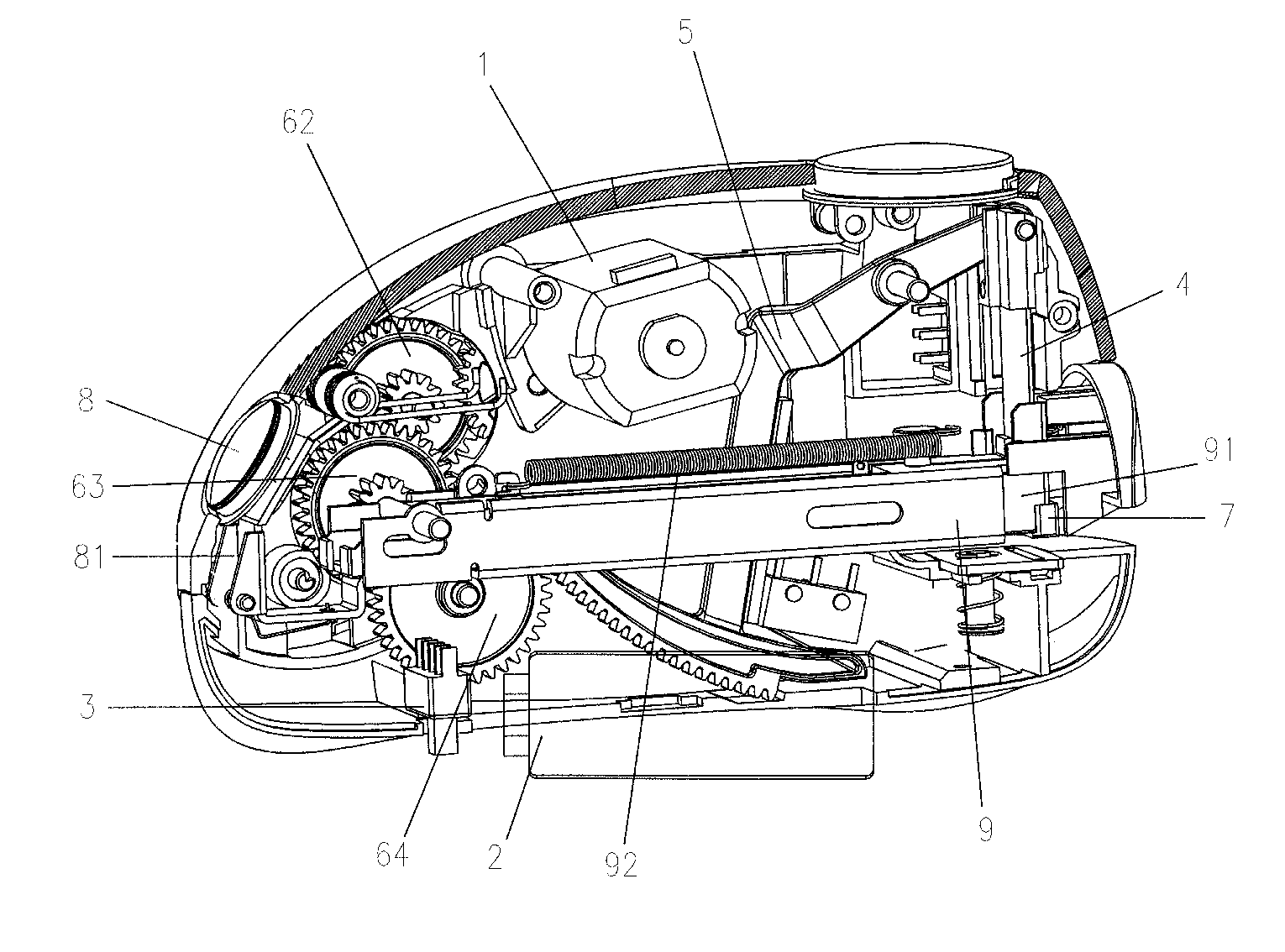
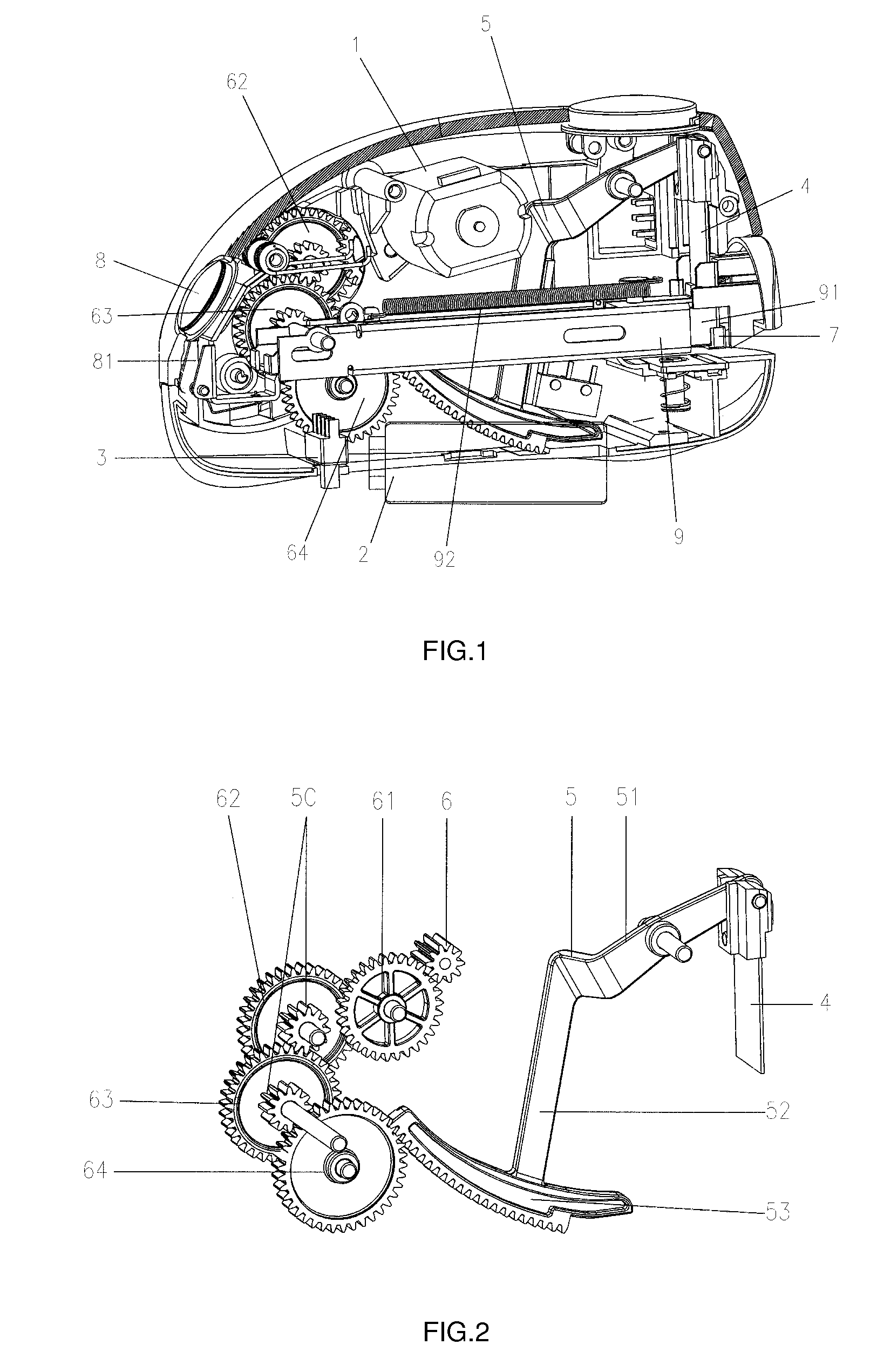
[0034]FIGS. 1 to 10 illustrate the detailed construction of an embodiment of the present invention. As illustrated in FIG. 1, the present invention comprises a body, an electric motor 1, a power supply 2, a power supply switch 3, a motion transmission mechanism having a gear cluster driven by the electric motor 1, and a staple driving mechanism having a driving blade 4 and a staple magazine driven by the motion transmission mechanism.

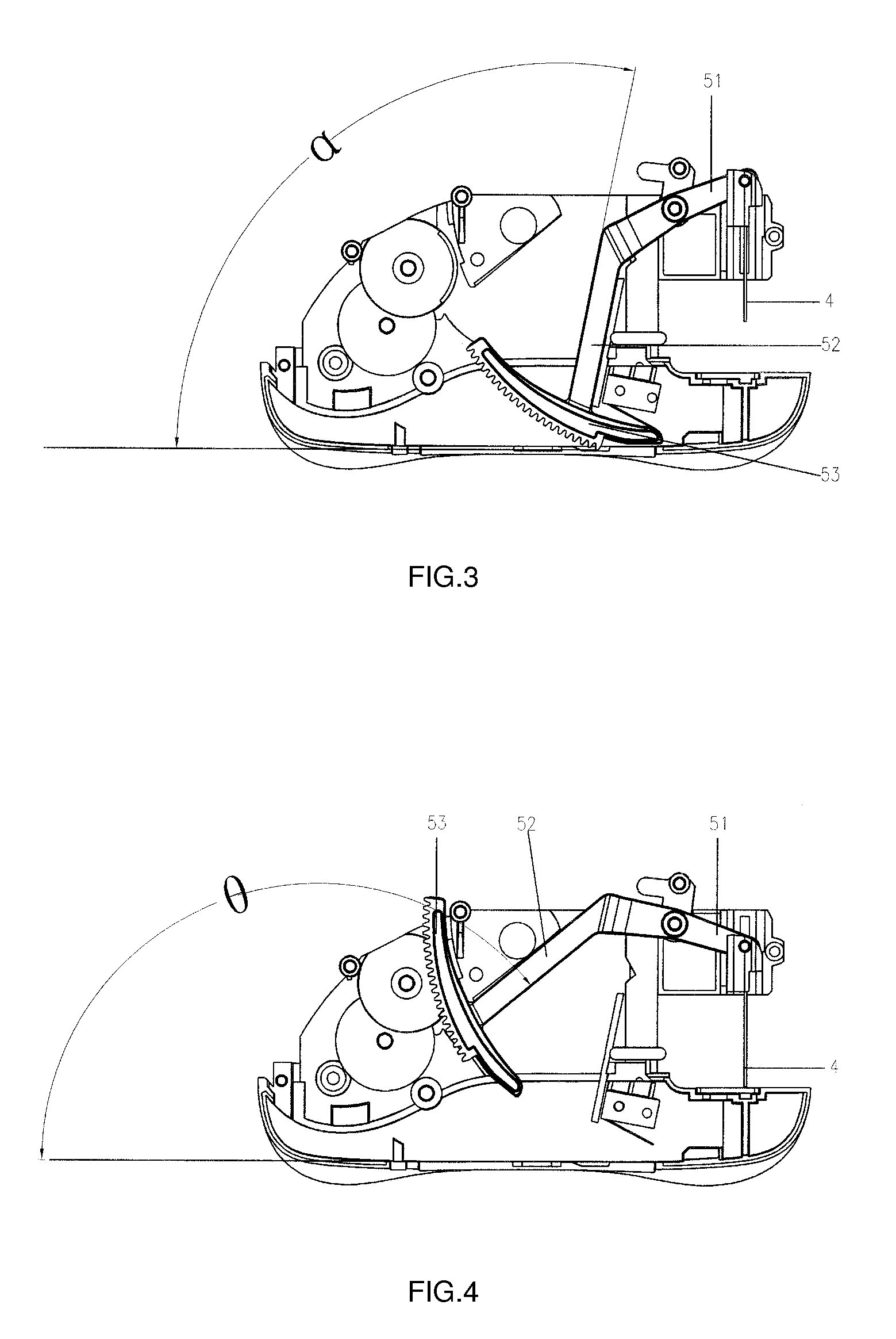
[0035]As illustrated in FIG. 2, the motion transmission mechanism comprises a rocking arm 5, and the rocking arm 5 is a crank which is composed of a connecting shaft 51 and a rocking shaft 52, the end of the connecting shaft 51 connects to the top of the driving blade 4, the end of the rocking shaft 52 is a gear 53, and the gear 53 of the rocking arm has teeth which mesh with teeth of at least one gear of the gear cluster, and in other ...


PUM

PropertyMeasurementUnit
pressure angleaaaaaaaaaa
angleaaaaaaaaaa
angleaaaaaaaaaa

Abstract

A stapler that requires exertion of less effort comprising a body, an electric motor, a power supply, a power supply switch, a motion transmission mechanism having a gear cluster driven by the electric motor, a staple driving mechanism having a driving blade and a staple magazine driven by the motion transmission mechanism. The motion transmission mechanism comprises a rocking arm, and the rocking arm is a crank which is composed of a connecting shaft and a rocking shaft. The end of the connecting shaft connects to the top of the driving blade. The end of the rocking shaft is a gear, and the gear of the rocking arm has teeth which mesh with teeth of at least one gear of the gear cluster. The motion transmission mechanism comprises a double pole changeover switch and a micro switch.

Description

BACKGROUND OF THE INVENTION[0001]The present invention relates to staplers and more particularly pertains to staplers of the kind which requires exertion of less effort.[0002]At present, the common electric staplers in the marketplace mainly achieve stapling by means of utilizing an electric motor to drive a gear cluster and then to drive a driving blade. A gear cluster generally requires a greater range of rotation and more time for stapling and resetting. Moreover, to increase the reliability of motion transmission, the prior art has some staplers which are complex in construction, and some of which have a gear cluster which is composed of five or more transmitting gears, thereby making the body of the staplers bulky, heavy and inconvenient for use.[0003]The prior art also provides some technical proposals which add a transmitting shaft or an eccentric wheel to the gear cluster so as to reduce the range of rotation of gears as required and to save the time required for stapling an...

Claims


Application Information

Patent Timeline
Patent Type & Authority Patents(United States)
IPC IPC(8): B27F7/19
CPCB25C5/15
Inventor CO, VICTOR
Owner COSIMEX H K
Why Eureka
Try Eureka