
Key generation source identification device, key generation source identification method, and computer readable medium

Inactive Publication Date: 2019-04-25
MITSUBISHI ELECTRIC CORP
View PDF0 Cites 5 Cited by
  • Summary
  • Abstract
  • Description
  • Claims
  • Application Information

AI Technical Summary

Benefits of technology

The key generation source identification device described in this patent helps to identify the source of an encryption key used by malware. It does this by analyzing the instructions and the encryption key used in the process of encryption. The device extracts a list of instructions that are dependent on the encryption key and checks if there are any functions in this list that can dynamically acquire information. If there is a function that can acquire dynamic information, the device gets that function as a potential key generation source. This makes it easier to decrypt encrypted files encrypted by malware.

Problems solved by technology

In recent years, targeted attacks to enterprises and government agencies aiming at theft of confidential information occur frequently, which is a serious security threat.
However, some of recent malware keep communication data secret by encrypting communication data by common key encryption.
Since communication data of such malware is recorded in an encrypted state, the communication data cannot be analyzed as it is.
Since this work requires reverse engineering of malware, it takes a huge amount of effort and time in general.

Method used


Image

  • Key generation source identification device, key generation source identification method, and computer readable medium
  • Key generation source identification device, key generation source identification method, and computer readable medium
  • Key generation source identification device, key generation source identification method, and computer readable medium

Examples


first embodiment

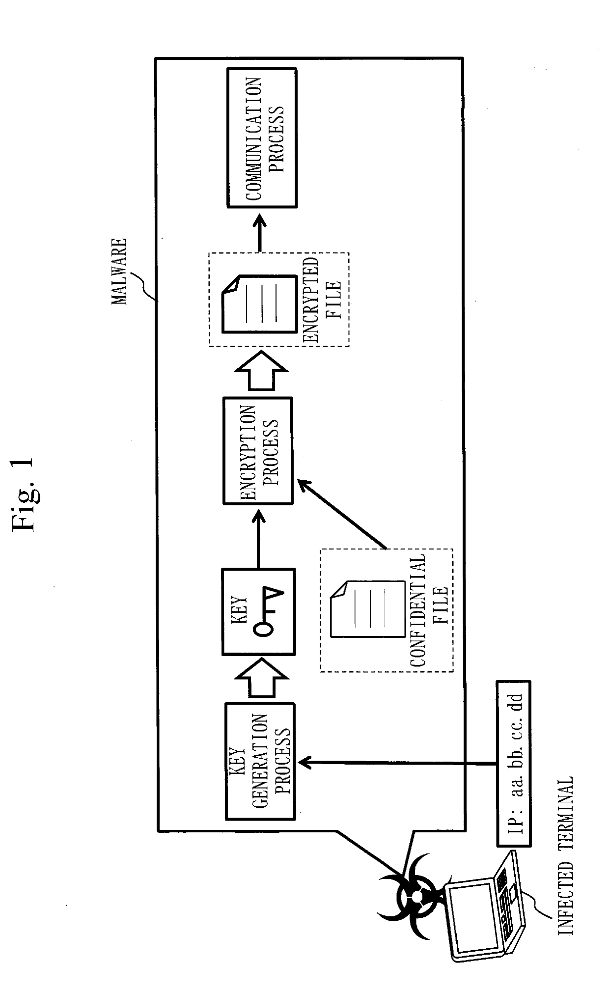
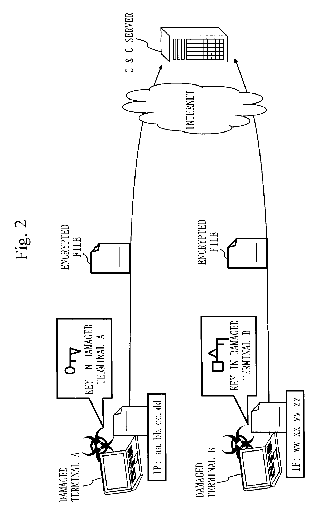
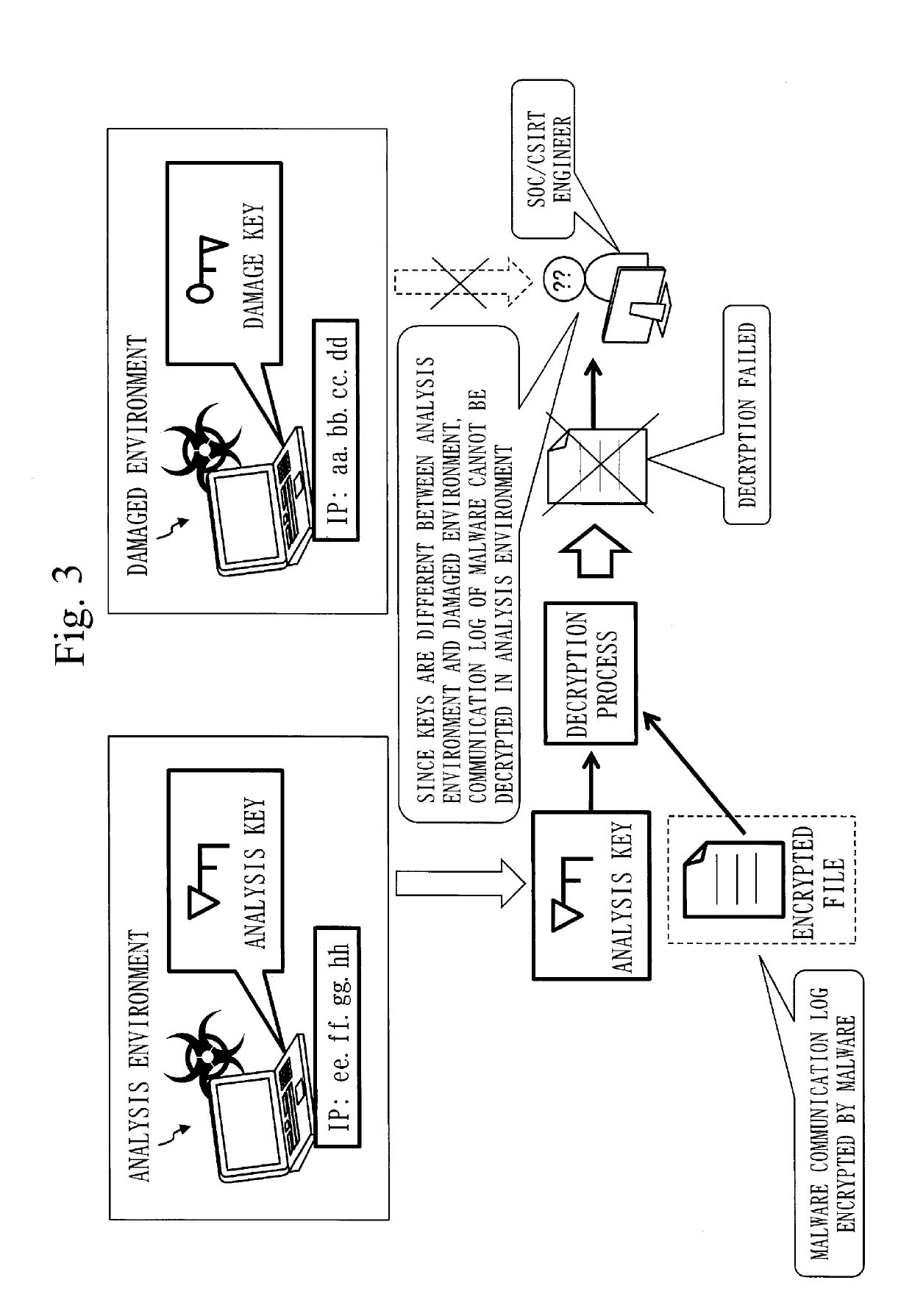
[0041]First, dynamic key generation will be described with reference to FIGS. 1 to 3.

[0042]FIG. 1 is a diagram illustrating an example in which malware dynamically generates a key.

[0043]Malware illustrated in this example generates a key to be used for encryption using an IP address on an infected terminal as a seed with which an encryption key is to be generated and encrypts a confidential file to steal. In this case, different keys are generated in different terminals and are used for an encryption process.

[0044]FIG. 2 is a diagram illustrating how different keys are generated at respective damaged terminals. Damaged terminals A and B are infected with the same malware, but keys used in the encryption process by malware are different.

[0045]FIG. 3 illustrates how a security operation center (SOC) / computer security incident response team (CSIRT) engineer requested to decrypt an encrypted file encrypted by malware cannot decrypt the encrypted file with an analysis key. As illustrated...

second embodiment

[0108]In the present embodiment, a difference from the first embodiment will be mainly described.

[0109]In the present embodiment, the same reference numerals are given to configurations similar to those described in the first embodiment and the description thereof will be omitted.

[0110]***Explanation of Configuration***

[0111]The configuration of a key generation source identification device 10a according to the present embodiment will be described with reference to FIG. 14.

[0112]In addition to the configuration of the first embodiment, the key generation source identification device 10a is further provided with a specification unit 33 in a key generation source acquisition unit 130. Additionally, the key generation source identification device 10a is further provided with a program database 142 in a storage unit 140. The other functional configuration and hardware configuration are the same as those in the first embodiment. Therefore, in the functional configuration of the key gener...

third embodiment

[0133]In the present embodiment, a difference from the first embodiment will be mainly described.

[0134]In the present embodiment, the same reference numerals are given to configurations similar to those described in the first embodiment and the description thereof will be omitted.

[0135]***Explanation of Configuration***

[0136]The configuration of a key generation source identification device 10b according to the present embodiment will be described with reference to FIG. 18.

[0137]In addition to the configuration of the first embodiment, the key generation source identification device 10b is provided with a program generation unit 150. The other functional configuration and hardware configuration are the same as those in the first embodiment. Therefore, in the functional configuration of the key generation source identification device 10b, the program generation unit 150 is added to the functional configuration of the key generation source identification device 10. Furthermore, in the...


PUM


Abstract

A key generation source identification device (10) is provided with a key identification unit (11) to cause malware to execute an encryption process, acquire an execution trace representing an execution status of the encryption process, and identify an encryption key used in the encryption process as an analysis key based on the execution trace, and an extraction unit (31) to extract, from the execution trace, a list of instructions on which the analysis key depends, as an instruction list. The key generation source identification device (10) is also provided with an acquisition unit (32) to determine whether a function called by a call instruction included in the instruction list is a dynamic acquisition function that acquires dynamic information dynamically changing and, when the function is the dynamic acquisition function, acquire the instruction list as a candidate of a key generation source which is at least a part of a program that generated the analysis key in the encryption process.

Description

TECHNICAL FIELD[0001]The present invention relates to a key generation source identification device, a key generation source identification method, and a key generation source identification program.BACKGROUND ART[0002]In recent years, targeted attacks to enterprises and government agencies aiming at theft of confidential information occur frequently, which is a serious security threat. Common targeted attacks begin with a mail with cleverly crafted text being transmitted to a target of attack. A document file containing malware is attached to this mail and a terminal is infected with the malware the moment a mail recipient opens this document at the terminal. An attacker controls this malware from a command server (C & C server: command and control server) on the Internet and looks for confidential information through a network inside a target organization to upload to the C & C server, thereby achieving the purpose. With the increasing severity of damage due to confidential inform...

Claims


Application Information

Patent Timeline
IPC IPC(8): G06F21/55G06F21/56H04L9/08
CPCG06F21/552G06F21/562G06F21/567G06F21/566H04L9/0861G06F2221/033H04L9/0866H04L9/0869
Inventor NISHIKAWA, HIROKINEGI, TOMONORIKAWAUCHI, KIYOTO
Owner MITSUBISHI ELECTRIC CORP
Learn More