Highly collimating reflector lens optic and light emitting diodes

a technology of reflector lens and light-emitting diodes, which is applied in the field of high-collimation reflector lens optics and light-emitting diodes, can solve the problems of light pollution, poor energy efficiency of previous beacon lights, and use of solar panels

Active Publication Date: 2011-12-15
DIALIGHT CORP
View PDF3 Cites 39 Cited by
  • Summary
  • Abstract
  • Description
  • Claims
  • Application Information

AI Technical Summary

Problems solved by technology

Previous beacon lights generally exhibit relatively poor energy efficiency, which can prohibit the use of solar panels to power the beacon light.
Previous beacon lights may also contribute to light pollution, i.e., direct light at angles undesirably above and below a specified plane.
Previous beacon lights may also be too large and heavy for climbers to carry and therefore may require additional machinery or manpower to be hoisted into position.
However, not all of the light emitted from a light source is reflected in a single reflector design.

Method used


Image

  • Highly collimating reflector lens optic and light emitting diodes
  • Highly collimating reflector lens optic and light emitting diodes
  • Highly collimating reflector lens optic and light emitting diodes

Examples


Embodiment Construction

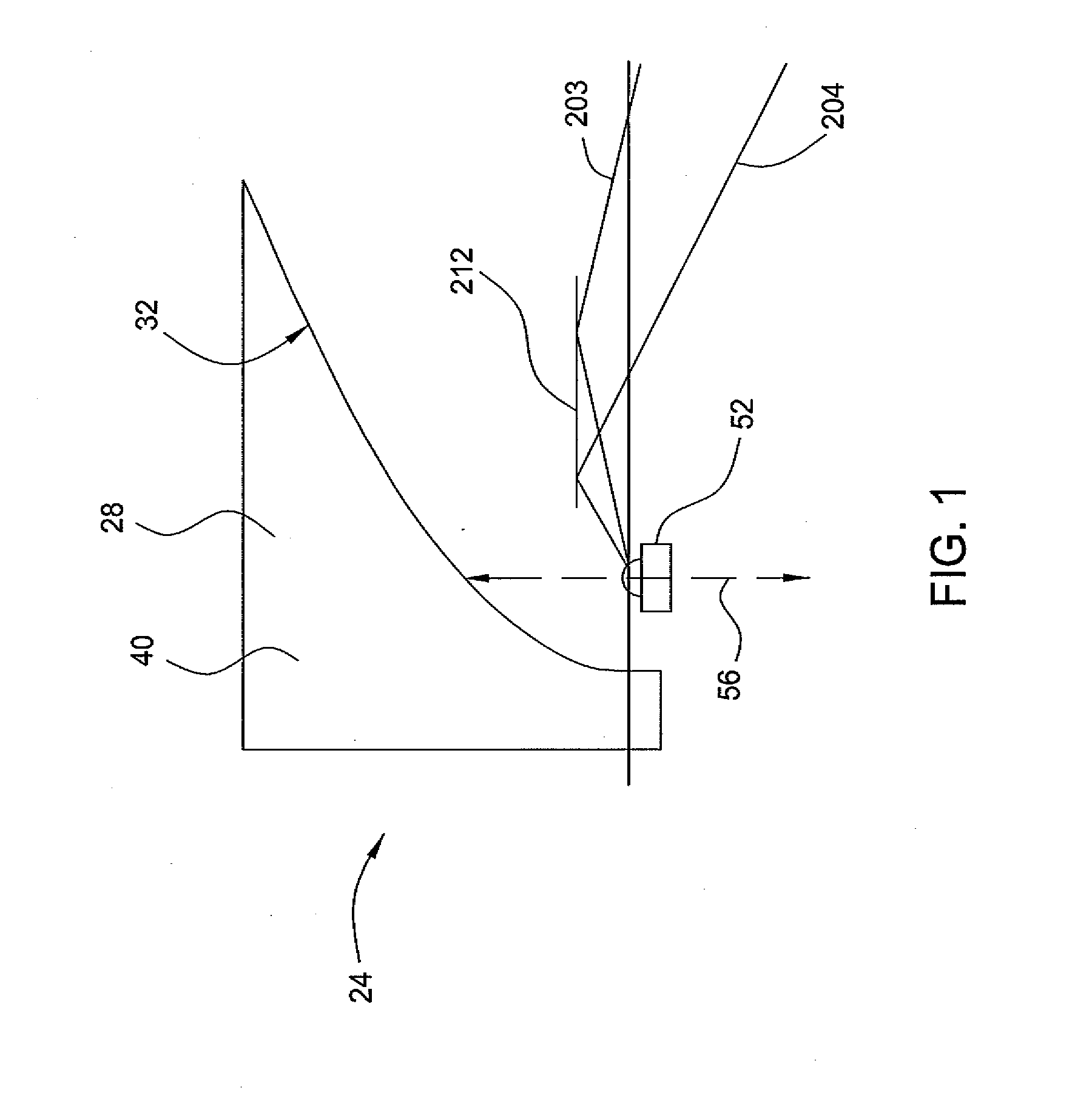
[0041]FIG. 1 depicts one embodiment of a side-cross-sectional view of a highly collimating optic and LED of the present disclosure. However, before a detailed discussion of FIG. 1 is provided, a detailed discussion of a reflector optic 24 is provided.

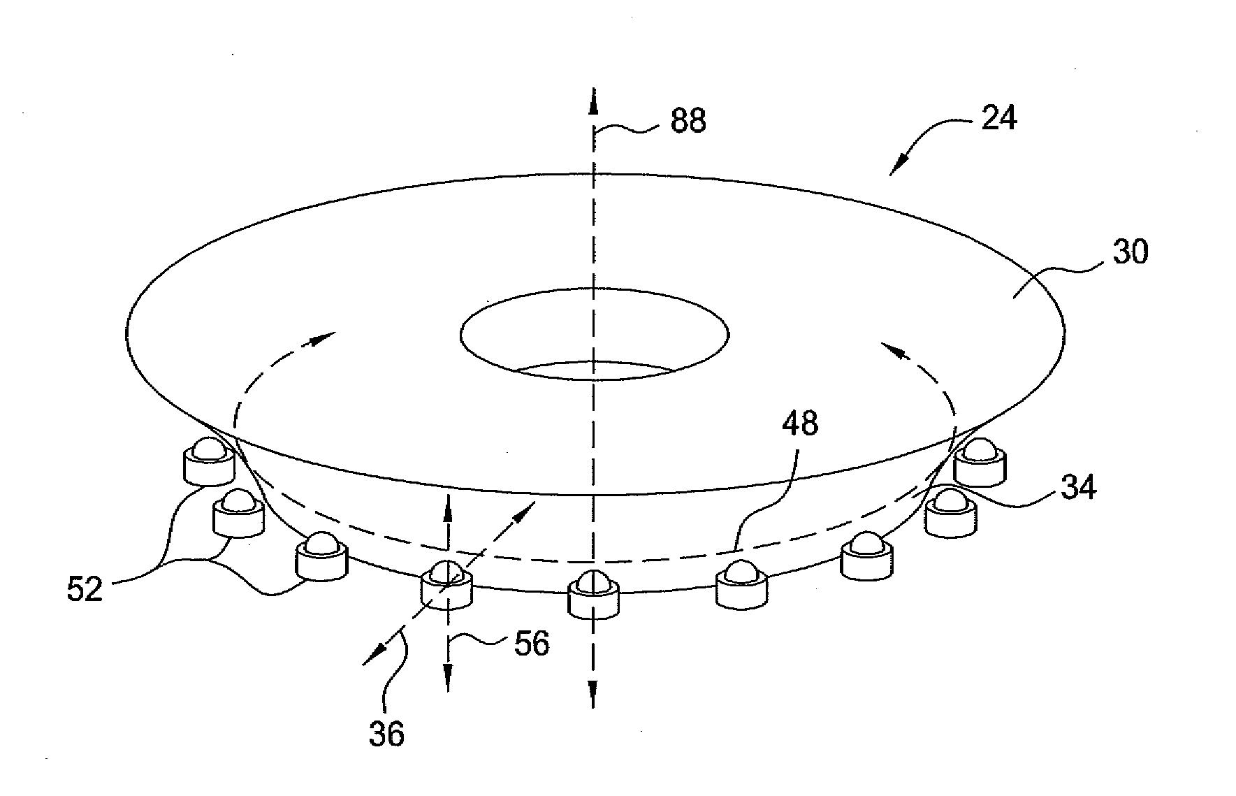
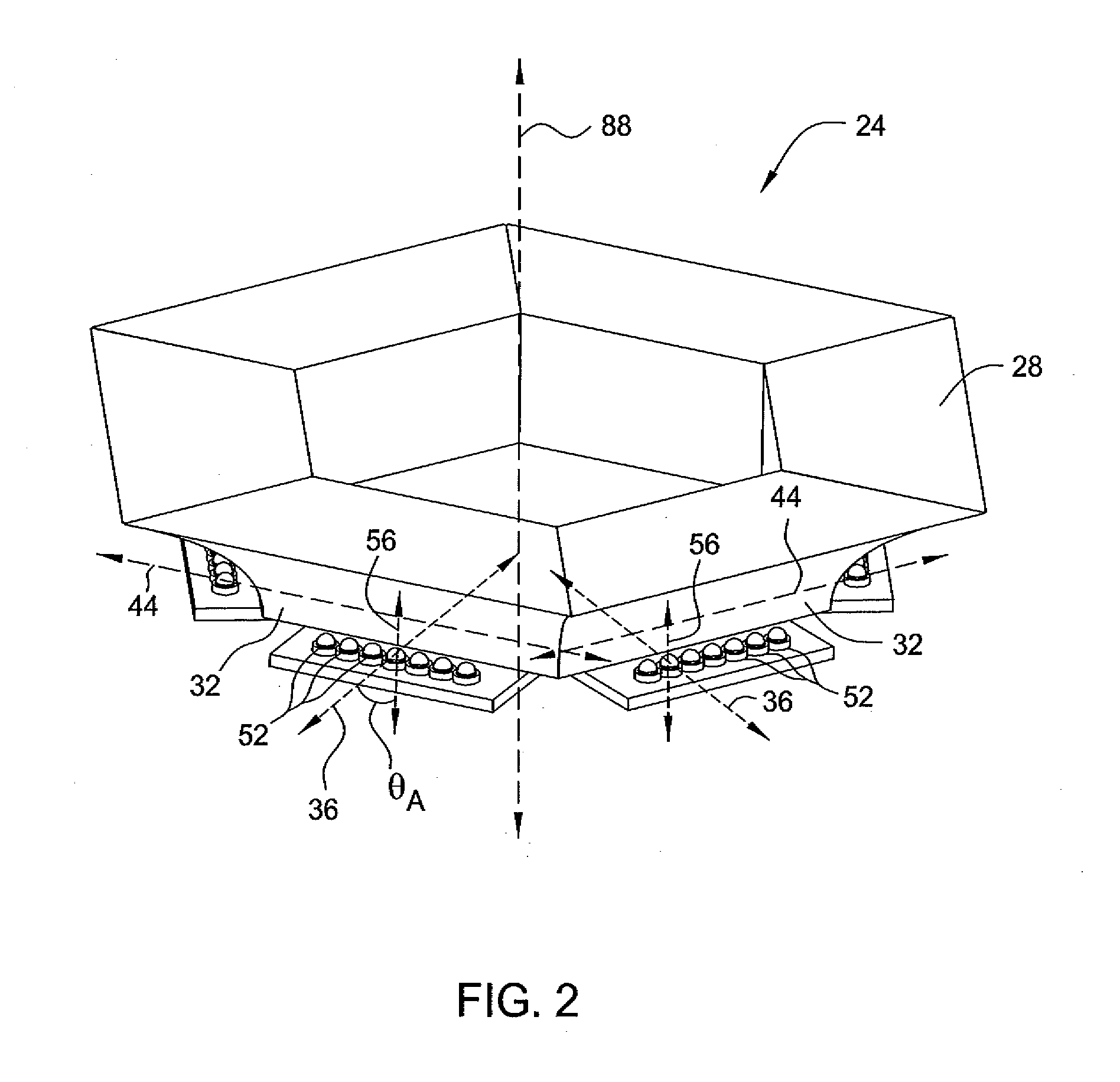
[0042]FIG. 2 depicts a perspective view of an embodiment of the LED reflector optic 24 according to the present invention. In one embodiment, the LED reflector optic 24 comprises a reflector 28 having a plurality of reflecting surfaces 32, i.e., a segmented reflector 28.

[0043]Each reflecting surface 32 comprises a cross-section 40 (as depicted in FIG. 8) which is projected along an associated linear extrusion axis 44. In one embodiment, the linearly projected cross-section 40 comprises a conic section. A conic section provides an advantageous reflected light intensity distribution. In one embodiment, the cross-section 40 of the reflecting surface 32 comprises at least one of: a conic or a substantially conic shape. In one embodiment, th...


PUM

PropertyMeasurementUnit
angleaaaaaaaaaa
anglesaaaaaaaaaa
anglesaaaaaaaaaa

Abstract

The present invention is directed to a beacon light with a light emitting diode (LED) optic. In one embodiment, the LED optic includes at least one LED comprising an LED plane, a first reflector positioned above the LED plane and comprising a curved cross-section, wherein the at least one LED is positioned approximately 90 degrees with respect to an optical axis of the first reflector and at least one second reflector positioned above the LED plane.

Description

BACKGROUND[0001]A beacon light such as, for example, an aircraft obstruction light, can be used to mark an obstacle that may provide a hazard to aircraft navigation. Beacon lights are typically used on buildings, towers, and other structures taller than about 150 feet. Previous beacon lights generally exhibit relatively poor energy efficiency, which can prohibit the use of solar panels to power the beacon light. Previous beacon lights may also contribute to light pollution, i.e., direct light at angles undesirably above and below a specified plane. Previous beacon lights may also be too large and heavy for climbers to carry and therefore may require additional machinery or manpower to be hoisted into position.[0002]Some beacon lights use a single reflector. However, not all of the light emitted from a light source is reflected in a single reflector design. As a result, the emitted light appears de-collimated as some of the light is emitted without reflection or collimation.SUMMARY O...

Claims


Application Information

Patent Timeline
Patent Type & Authority Applications(United States)
IPC IPC(8): F21V1/00F21V19/00
CPCF21V5/02Y10T29/49826F21V7/0008F21V7/0025F21V13/04F21W2111/00F21W2111/06F21Y2101/02F21Y2103/022B64F1/20G02B19/0066G02B19/0019G02B19/0023B64D2203/00Y10S362/80F21V5/045F21Y2113/00F21Y2103/33F21Y2115/10
Inventor PECK, JOHN PATRICK
Owner DIALIGHT CORP
Why Eureka
Try Eureka