Wafer-level light emitting diode package and method of fabricating the same

a technology of light-emitting diodes and wafer-level, which is applied in the direction of semiconductor/solid-state device manufacturing, electrical apparatus, semiconductor devices, etc., can solve the problems of increasing time and cost for manufacturing led modules, deteriorating luminous efficiency of led modules, and difficulty in miniaturizing and satisfactory heat dissipation of conventional led packages including lead frames or printed circuit boards. achieve the effect of reducing manufacturing time and cost, high efficiency and improving heat dissipation

Active Publication Date: 2012-03-29
SEOUL SEMICONDUCTOR
View PDF4 Cites 430 Cited by
  • Summary
  • Abstract
  • Description
  • Claims
  • Application Information

AI Technical Summary

Benefits of technology

[0014]Exemplary embodiments of the invention also provide a wafer-level LED package and a method of fabricating the same, which has high efficiency and exhibits improved heat dissipation.
[0015]Exemplary embodiments of the invention also provide a method of fabricating an LED package, which may reduce manufacturing time and cost of an LED module.
[0016]Exemplary embodiments of the invention also provide an LED module and a method of fabricating the same, which has high efficiency and exhibits improved heat dissipation.

Problems solved by technology

However, it may be difficult to achieve miniaturization and satisfactory heat dissipation of the conventional LED package including the lead frame or printed circuit board.
Furthermore, luminous efficiency of the LED may be deteriorated due to absorption of light by the lead frame or the printed circuit board, electric resistance heating by the lead terminals, and the like.
In addition, the chip fabrication process, the packaging process, and the modulation process may be separately carried out, thereby increasing time and costs for manufacturing the LED module.
Since the AC-LED includes light emitting cells on a growth substrate, for example, on a sapphire substrate, the AC-LED restricts the structure of the light emitting cells and may limit improvement of light extraction efficiency.

Method used


Image

  • Wafer-level light emitting diode package and method of fabricating the same
  • Wafer-level light emitting diode package and method of fabricating the same
  • Wafer-level light emitting diode package and method of fabricating the same

Examples


Embodiment Construction

[0037]The invention is described more fully hereinafter with reference to the accompanying drawings, in which exemplary embodiments of the invention are shown. This invention may, however, be embodied in many different forms and should not be construed as limited to the exemplary embodiments set forth herein. Rather, these exemplary embodiments are provided so that this disclosure is thorough and will fully convey the scope of the invention to those skilled in the art. In the drawings, the sizes and relative sizes of layers and regions may be exaggerated for clarity. Like reference numerals in the drawings denote like elements.

[0038]It will be understood that when an element such as a layer, film, region or substrate is referred to as being “on” another element, it can be directly on the other element or intervening elements may also be present. In contrast, when an element is referred to as being “directly on” another element, there are no intervening elements present.
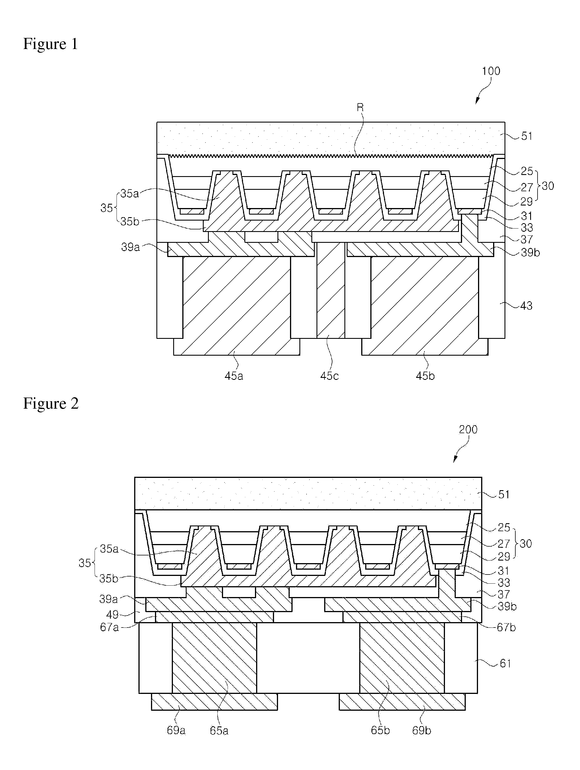
[0039]FIG. 1 ...


PUM


Abstract

Exemplary embodiments of the present invention provide a wafer-level light emitting diode (LED) package and a method of fabricating the same. The LED package includes a semiconductor stack including a first conductive type semiconductor layer, an active layer, and a second conductive type semiconductor layer; a plurality of contact holes arranged in the second conductive type semiconductor layer and the active layer, the contact holes exposing the first conductive type semiconductor layer; a first bump arranged on a first side of the semiconductor stack, the first bump being electrically connected to the first conductive type semiconductor layer via the plurality of contact holes; a second bump arranged on the first side of the semiconductor stack, the second bump being electrically connected to the second conductive type semiconductor layer; and a protective insulation layer covering a sidewall of the semiconductor stack.

Description

CROSS-REFERENCE TO RELATED APPLICATION[0001]This application claims priority from and the benefit of Korean Patent Application No. 10-2010-0092807, filed on Sep. 24, 2010, and Korean Patent Application No. 10-2010-0092808, filed on Sep. 24, 2010, which are hereby incorporated by reference for all purposes as if fully set forth herein.BACKGROUND OF THE INVENTION[0002]1. Field of the Invention[0003]The invention relates to a light emitting diode package and a method of fabricating the same and, more particularly, to a wafer-level light emitting diode package and a method of fabricating the same.[0004]2. Description of the Background[0005]A light emitting diode (LED) is a semiconductor device that includes an N-type semiconductor and a P-type semiconductor, and emits light through recombination of holes and electrons. Such an LED has been used in a wide range of applications such as display devices, traffic lights, and backlight units. Further, considering the potential merits of lower...

Claims


Application Information

Patent Timeline
Patent Type & Authority Applications(United States)
IPC IPC(8): H01L33/50H01L27/15H01L33/38H01L33/58
CPCH01L27/153H01L33/0079H01L33/20H01L33/38H01L33/382H01L33/46H01L33/50H01L2933/0016H01L33/486H01L2924/0002H01L33/62H01L33/10H01L2924/00H01L33/0093H01L33/42H01L33/502H01L33/44H01L33/405H01L33/24H01L33/507H01L33/642H01L2933/0025H01L2933/0033H01L2933/0041H01L2933/0075H01L27/15H01L33/22H01L33/58H01L33/505H01L33/385H01L33/007H01L33/0095H01L33/06H01L33/12H01L33/32H01L33/56H01L33/647H01L2933/005H01L2933/0066
Inventor SEO, WON CHEOLKAL, DAE SUNG
Owner SEOUL SEMICONDUCTOR
Why Eureka
Try Eureka