
Linear lighting apparatus with improved heat dissipation

a lighting apparatus and linear technology, applied in lighting and heating apparatus, lighting support devices, instruments, etc., can solve the problems of inefficient use of reflective materials, inefficient use of materials and designs, and inability to deliver continuous uninterrupted beams of light, so as to improve the dissipation of heat

Inactive Publication Date: 2006-07-06
IO LIGHTING
View PDF24 Cites 425 Cited by
  • Summary
  • Abstract
  • Description
  • Claims
  • Application Information

AI Technical Summary

Benefits of technology

[0011] The present invention also provides for a method for improving the heat dissipation in a linear lighting apparatus. The method includes emitting light from a plurality of light emitting diodes, contacting a plurality of primary optical assemblies with the light emitting diodes, refracting the light in each of the primary optical assemblies towards a secondary optical assembly, refracting the light in a secondary optical assembly so that the light is directed in at least one of a desired direction and a desired distribution, and dissipating thermal energy generated by the light emitting diodes.

Problems solved by technology

Currently, the only light source that can deliver this continuous, uninterrupted beam of light is fluorescent light sources.
However, these lighting apparatuses typically use very inefficient materials and designs for transmitting the light produced by the LEDs.
The use of a reflective material is a very inefficient manner in which to harness and direct light emitted by LEDs.
Specifically, the use of reflective materials is very difficult to control the direction of emitted light in very tight spaces.
In addition, reflective materials lose a considerable amount of light emitted from the LEDs in trying to reflect the light in a given direction.
The use of refractory materials does provide a higher lighting efficiency than the use of reflective materials, but is far from optimized in current apparatuses and methods.
The use of a singular refractive assembly does not optimize the amount of light harnessed by the assembly and emitted by the apparatus.
The light that does not enter into the optical assembly is therefore lost.
Therefore, current linear lighting apparatuses are inefficient in their transmission of light from a light source to the atmosphere around the lighting apparatus.
Such an outdoor application requires considerable luminous flux from a lighting apparatus.
However, as described above, each LED produces a considerable amount of heat.
Increasing the number of LEDs in an apparatus only adds to the amount of heat present in the apparatus.
This increased heat can drastically shorten the lifespan of the lighting apparatus.
Current linear lighting apparatuses do not efficiently dissipate heat from the LEDs.
Due to space constraints, the lighting apparatuses must be small in size, or profile.
However, as described above, the luminous flux output of the apparatuses must be considerable.

Method used


Image

  • Linear lighting apparatus with improved heat dissipation
  • Linear lighting apparatus with improved heat dissipation
  • Linear lighting apparatus with improved heat dissipation

Examples


Embodiment Construction

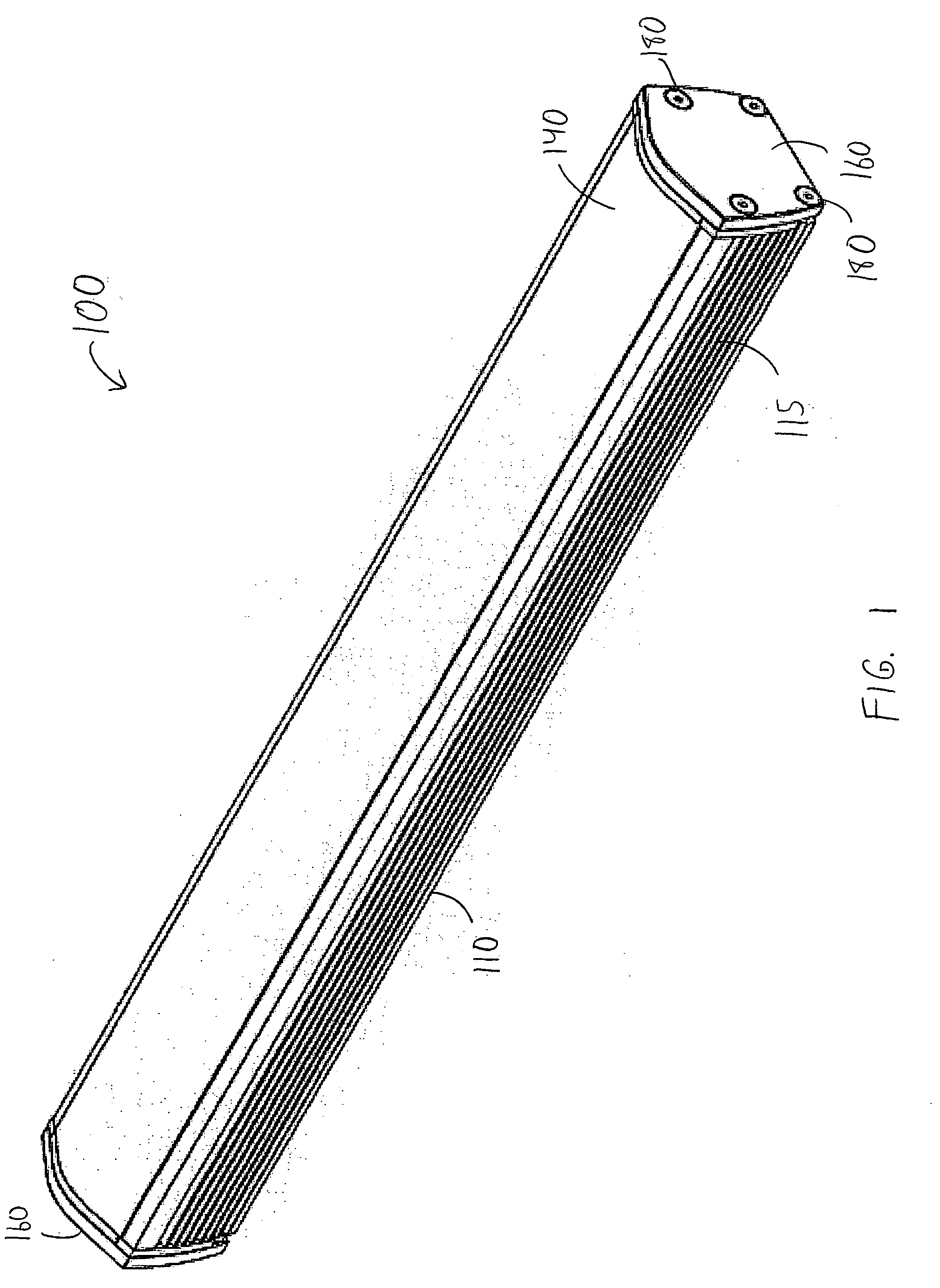
[0025]FIG. 1 illustrates a perspective view of a linear lighting apparatus 100 in accordance with an embodiment of the present invention. Linear lighting apparatus 100 may be used as a low voltage linear accent luminaire. Apparatus 100 may be used in both indoor and outdoor applications. In addition, apparatus 100 may be customizable in length. For example, based on at least the selected lengths of some of the various components of apparatus 100, the length of apparatus 100 may be any nominal length up to 108″, for example. However, other lengths are possible and within the scope of the present invention.

[0026] Apparatus 100 is capable of and configured to refract light produced from a plurality of LEDs in such a way as to produce a linear beam of light. In other words, LEDs normally produce singular points of light. However, apparatus 100 refracts the light produced by the LEDs so that apparatus 100 produces a continuous linear beam of light emanating along a length of apparatus 1...


PUM


Abstract

The present invention provides a linear lighting apparatus with improved heat dissipation and a method for improving the heat dissipation in a linear lighting apparatus. The apparatus includes a plurality of light emitting diodes, a plurality of primary optical assemblies and an apparatus housing. The primary optical assemblies are each in contact with one of the plurality of light emitting diodes. The primary optical assemblies and a second optical assembly are configured to refract the light so as to create a linear light source emanating from the apparatus. The apparatus housing is configured to dissipate thermal energy from the light emitting diodes.

Description

BACKGROUND OF THE INVENTION [0001] The present invention generally relates to linear lighting apparatuses. More specifically, the present invention describes an apparatus and method for increased lighting efficiency in a linear lighting apparatus with a plurality of optical assemblies. [0002] Many linear lighting apparatuses exist in the lighting industry today. Several of these apparatuses use light-emitting diodes (“LEDs”) as light sources. LEDs are individual point light sources that each delivers a singular beam of light. When organized in a linear array, the individual beam patterns from each LED are very apparent, resulting in a “scalloping” effect. Eliminating this effect when grazing building facades or glass, for example, is highly desirable. Currently, the only light source that can deliver this continuous, uninterrupted beam of light is fluorescent light sources. However, LEDs are preferred as light sources over fluorescent lights as LEDs can produce a more concentrated b...

Claims


Application Information

Patent Timeline
IPC IPC(8): F21V5/00F21S4/00
CPCF21S4/008F21V29/767F21V5/02F21V5/04F21V15/013F21V17/101F21V17/104F21V17/164F21V19/001F21V19/042F21V29/004F21W2131/107F21Y2101/02F21Y2103/003G09F13/22G09F19/12G09F2013/0436G09F2013/0495G09F2013/222G09F2019/223F21V5/008F21V19/04F21V29/504F21S4/28F21Y2103/10F21Y2115/10G09F13/0436G09F13/0495F21L14/026F21V15/01F21V17/16
Inventor REO, ANNWATT, GRAEME
Owner IO LIGHTING
Learn More