Structure for operating pivot switches of multi-function switch assembly

Inactive Publication Date: 2011-12-22
ALPS ELECTRIC KOREA
View PDF0 Cites 12 Cited by
  • Summary
  • Abstract
  • Description
  • Claims
  • Application Information

AI Technical Summary

Benefits of technology

[0021]Another object of the present invention is to prevent interference in a vertical direction between the actuation lever and a slider when a pivot switch is manipulated, and improve a feeling of manipulation, facilitate the manip

Problems solved by technology

Accordingly, the conventional multi-function switch apparatus is problematic in that the switch operation of the joystick method and the switch operation of the push method are complicated and the number of components is increased.
However, the joystick lever 13 made of metal material is problematic in that it increases the weight of the switch apparatus and also raises the manufacturing cost of the switch apparatus.
Accordingly, the conventional apparatus is problematic in that the construction is complicated, assembly is poor, and the manufacturing cost is raised owing to an increase of t

Method used


Image

  • Structure for operating pivot switches of multi-function switch assembly
  • Structure for operating pivot switches of multi-function switch assembly
  • Structure for operating pivot switches of multi-function switch assembly

Examples


Embodiment Construction

[0032]Some exemplary embodiments of the present invention will now be described in detail with reference to the accompanying drawings.

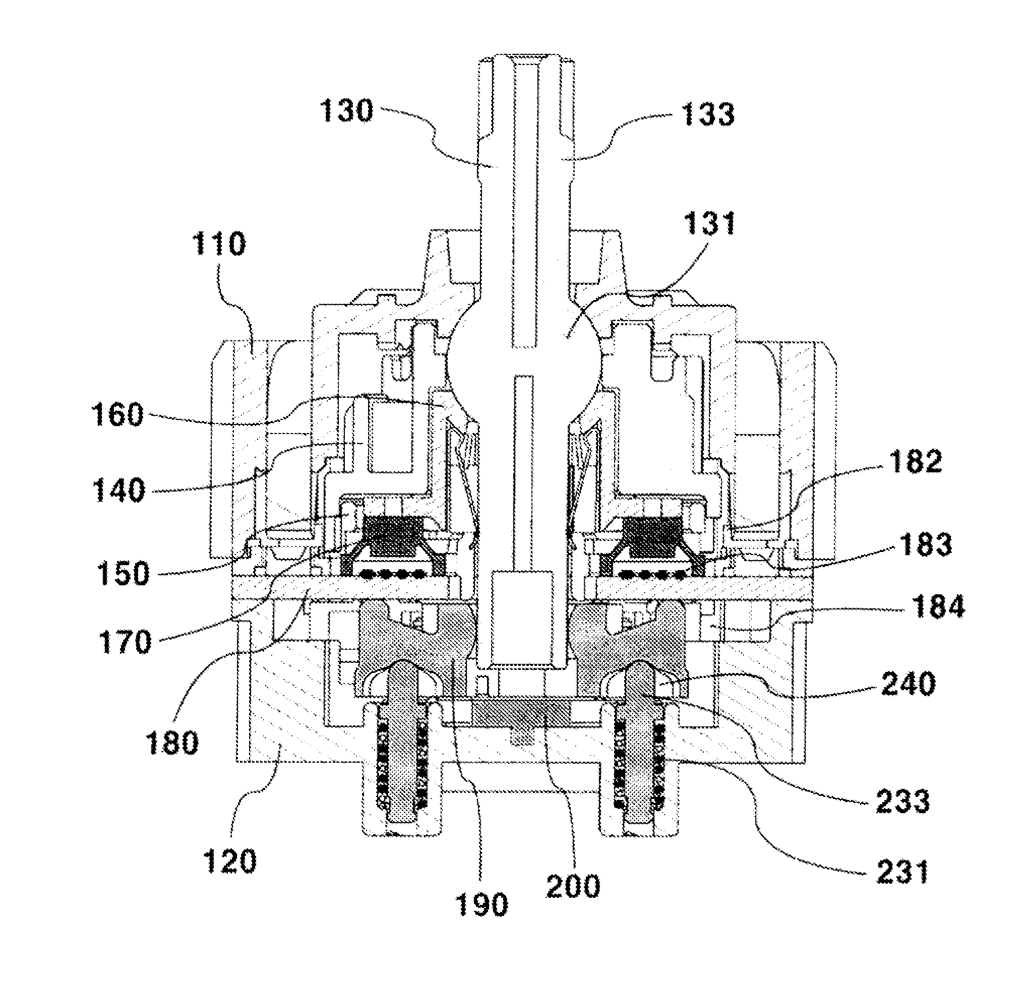
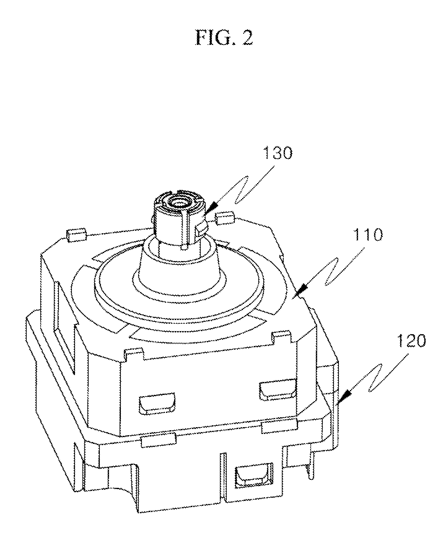
[0033]As shown in FIGS. 2 to 4, a multi-function switch assembly of the present invention is equipped with upper and lower casings 110 and 120 which are coupled together to face each other.

[0034]An actuation lever 130 is configured to penetrate the upper casing 110 and the lower casing 120 from the top of the upper casing 110 toward the bottom of the lower casing 120 and connected to the upper and lower casings 110 and 120. A rotation holder 140 is axially connected to the actuation lever 130 on the lower side of the upper casing 110 and rotated 360° when the actuation lever 130 is rotated.

[0035]A fixing holder 150 is fixed between the upper and lower casings 110 and 120 under the rotation holder 140 and configured to support the rotary motion of the rotation holder 140. A push holder 160 is axially connected to the center of the fixing holder 150 and...


PUM


Abstract

A multi-function switch assembly configured to implement a push switch function is provided. A structure for operating pivot switches of the multi-function switch assembly includes a Printed Circuit Board (PCB) disposed between upper and lower casings coupled together to face each other, push. switches and rotary switches mounted on the PCB, pivot switches mounted on a bottom of the PCB, a pair of sliders disposed to cross each other at a bottom of the lower casing and configured to laterally ground and operate the pivot switches in eight directions while operating in conjunction with a manipulation direction of the actuation lever, and alignment means configured to elastically support at least one of bottoms of the pair of sliders so that restoring force of a neutral state is generated.

Description

CROSS-REFERENCE TO RELATED APPLICATION[0001]Priority to Korean patent application number 10-2010-0058959 filed on Jun. 22, 2010, the entire disclosure of which is incorporated by reference herein, is claimed.BACKGROUND OF THE INVENTION[0002]1. Field of the Invention[0003]The present invention relates to a multi-function switch assembly configured to implement a push switch function, a rotary switch function, and a pivot switch function at the same time and, more particularly, to a structure for operating the pivot switch of a multi-function switch assembly, which is capable of improving a feeling of manipulation of the pivot switch and also preventing interference with other switch functions.[0004]2. Description of the Related Art[0005]In general, a multi-function switch apparatus is applied to navigation systems or audio systems for vehicles and configured to operate several switches using one switch apparatus.[0006]This multi-function switch apparatus includes a switch of a joysti...

Claims


Application Information

Patent Timeline
IPC IPC(8): H01H13/70
CPCG05G9/047H01H2025/043H01H25/041
Inventor YANG, DAE YEONKIM, KI WONKIM, JONG ROG
Owner ALPS ELECTRIC KOREA
Why Eureka
Try Eureka